Updated: 17-Jul-2023
Under construction
(Being translated)
Rolls Royce is perhaps the most important current company that builds aviation engines of all kinds that are operated by civil companies and air forces around the world.
-It is known for manufacturing the best, most famous and prestigious automobiles ever known.
-But it all began around 1884 when Frederick Henry Royce, a miller's son, was studying at a night school.
-At the turn of the century he bought a second-hand foreign car and finding deficiencies and not being satisfied with it, he decided to build one on his own.
-It exceeded in running smoothly over the best European engines of the time. It had two cylinders.
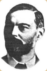
“Frederick Henry Royce”
-In 1904 he founded his own company in Manchester named Royce Ltd.
-On the other hand, the Honorable Charles Stuart Rolls, a sportsman from an important family with great media, sold European cars in London.
-He was also an engineer, graduated from Cambridge. At first he decided to sell Royce cars as well.
-In 1906 they came together and founded "Rolls-Royce Ltd", beginning to manufacture cars with 2, 3, 4 and 6-cylinder engines.
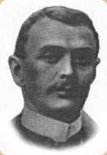
“Charles Stuart Rolls”
-Rolls was in charge of the sales of the vehicles that were designed and built by perfectionist Royce, being the "Silver Ghost" the most famous at that time, which were manufactured for 19 years.
-A brand logo was made with the two superimposed Rs, within a polygonal field and a lion on it. The letters were in red.
“Rolls-Royce logo”
-It occurred that Rolls died in 1910 when his Wright plane crashed because its tail broke off. He was aged 32 then.
-For this reason, Royce changed the color red in the logo to mourning black, with which it has survived until today, although it would later be simplified to the central vertical rectangle.
-Royce would also suffer a serious illness that would keep him convalescing for the rest of his life, until 1933 when he would die.
-While Rolls had been an aviation enthusiast, Royce had no interest.
-But when the First World War began, the Rolls-Royce factory in Derby, in the English Midlands, was mobilized, initially receiving the order to build a French Renault aviation engine.
-Not being satisfied with the technical solutions and due to his level of experience, he decided to build his own 200 HP engine, thus entering the private aeronautical field in 1914.
-This engine that would contribute to English success started with 200, 225 and 360 HP.
-Although it seems that the first design corresponded to the “Falcon” (Sept. 1914) of 205/280 HP.
-The first Falcon ran in March 1915, and the “Eagle” in August.
-Certainly, initially choosing a 200 HP engine was a request from the Admiralty.
-Although some articles give the Eagle as the first engine, it can be said that the first with an exclusive aeronautical design was the Falcon, since it was more advanced until in that same year 1915 the three engines came out.
-Since the "Hawk" also came out on this principle, based on the "Ghost" motor car, with 6 cylinders in line.
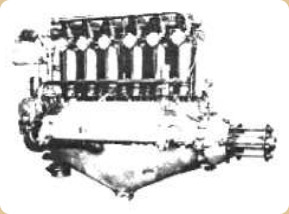
“Hawk”
-The Hawk gave 100 HP at 1,700 rpm. The cylinders were 4 inches in bore by 6 in stroke.
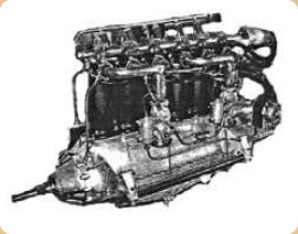
“RR Hawk, 100 HP”
-The Falcons -and in parallel the Eagles- had 12 cylinders in V, two Claudel-Hobson carburetors at the front, feeding manifolds in the center of said V, and the exhausts were on the outside of the engine.
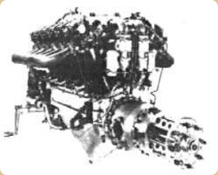
“RR, Falcon”
-The water outlet from each cylinder initially worked through the "thermosiphon" method, that is, the hot water rose and from there to the radiator. A pump would help circulation.
-The Falcon II already achieved 280 HP (with 4 carburetors, two at the front and two at the rear) and it was the typical engine that powered the Bristol Fighter. All Falcons had reduction gear.
-The Falcon III gave 275 HP at 2,000 rpm. Brazil-Straker also manufactured them under license in this early WWI era.
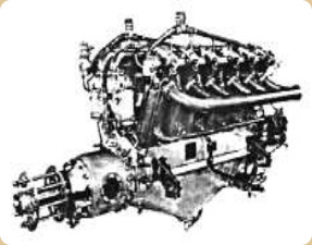
“RR, Falcon II”
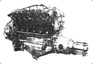
“RR, Falcon III”
-The manufacture of the Falcon engines continued after the war until the year 1927.
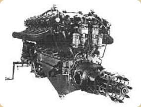
“RR, Eagle”
-Its contemporary Eagle engine, like the previous ones, had separate individual cylinders in Mercedes style.
-The gear was also epicyclic with inspection covers on both sides.
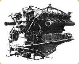
“RR, Eagle rear view”
-With the Eagle the main characteristics of the Falcon would be maintained.
-We see an Eagle variant with the very ascending and cascading water outlet towards the radiator/s and with a manifold for each line of cylinders.
-The oil pan also varies.
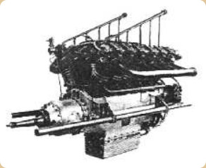
“RR, Eagle variant”
-Several versions were made such as VI, VII, VIII and IX in the range of 350/375 HP.
-It was an important engine. As a curiosity, on August 5, 1918, Major Egbert Cadbury and Captain Robert Leckie flew on a DH4 with a 375 HP R-R "Eagle VIII" engine and destroyed the last German Zeppelin of the time, the L-70 that commanded Captain Peter Strasser.
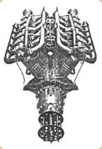
“Eagle with two central carburetors”
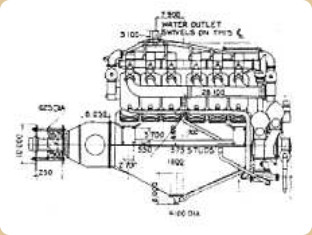
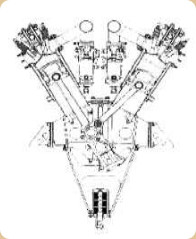
“Eagle with four carburetors”
-This model had four magnetos, two on each side at the rear.
-The Eagle VIII was also used on the Vickers Vimy, which with four engines crossed the North Atlantic in 1919. At the end of the same year another similar aircraft arrived in Australia from England.
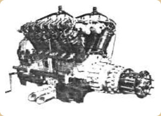
“R-R, Eagle IX”
-The IX series changes the gearbox for one without inspection covers and with a more robust appearance, increasing power to 360 HP. The carburetors are changed in amount from four to two, and they are neither at front nor at the rear. And neither in the V center. They are located under the engine, one on each side.
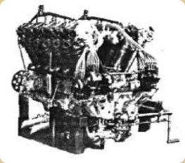
“Rolls-Royce Eagle IX, rear view”
-At the rear we can see the four magnetos and the corresponding wiring towards the spark plugs.
-It has a crank starter handle. and we can also see the water pump at the lower rear part.
-Now we see how the engines were broken-in in the field. This is a Rolls Royce Eagle.
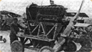
“Break-in bench for the Eagle”
-During 1917 a larger engine appeared. It was derived from the Eagle with four valves per cylinder and 12 cylinders in V, and was called "Condor". Its powers started with 550/600 HP.
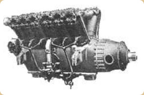
“RR, Condor”
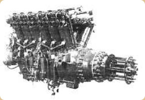
“RR, Condor with hub”
-It had the possibility of using an electric starter. In later models it was modernized, especially the reduction gear, the connecting rod system and the distribution.
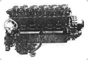
“Condor III”
-The Condor IIIA gave 725 HP at 1,900 rpm. It was installed on several airships including the R-100, with a total of six engines.
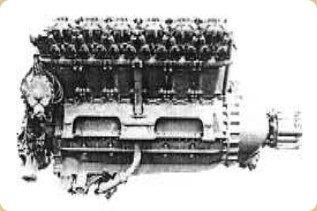
“RR, Condor IV”
-The Condor IV that gives 650 HP is reflected in the above illustration. Probably with a direct transmission to the propeller.
-About 325 Condor engines were built in total. An interesting test was carried out around 1932 in which a Condor was transformed into a Diesel. It was the result of the collaboration provided by Harry Ricardo (see).
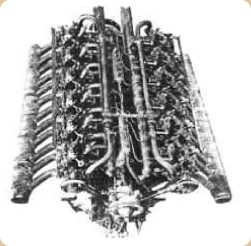
“Condor Diesel”
-In the photo taken from above the engine we clearly see the two monobloc diesel injection pumps in the center of the V, arranged in tandem. It flew in 1933 giving 480 HP at 1,900 rpm.
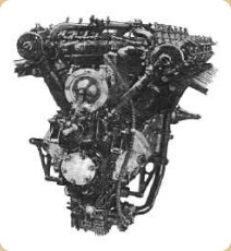
“Condor Diesel, rear view”
-After the Condor engines, Rolls-Royce stops manufacturing separate cylinders to change to cylinder blocks.
-At the time of the Condor, formulas of V-16 and W-18 were studied.
-As a consequence of the fight for competition, in 1925 it appears, almost circumstantially and with the name of Eagle again, the X-16. It had 16 cylinders in “X”, and it was the Eagle XVI model, giving 500 HP.
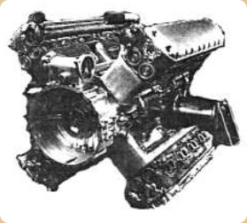
“RR, Eagle XVI”
-The competition mentioned was the one offered at that time by Fairey “Felix”, (see).
-They thought of a bigger engine, the Eagle XX, but good results were already being obtained with the classic V-12s. In fact in 1926 the XX was a V-12.
-Towards 1927 the “F” series appear with the F10 version that gave 480 HP.
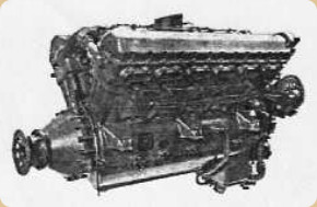
“RR, F10”
-The “F” engines would be the “Kestrel” generators, in fact “F engine or Kestrel” is often mentioned.
-It was offered supercharged or non-supercharged, with powers between 490 and 600 HP and was manufactured between 1927 and 1938.
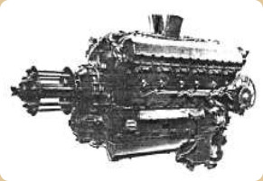
“F, normally aspirated"
-The main characteristic of the F is that they began to use cylinder blocks instead of single cylinders.
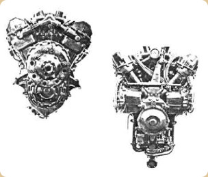
“F, front and rear”
-In 1928 the Fs came out, and in 1930 the Kestrel itself with the possibility of delivering 750 HP at 14,500 feet of altitude and at 3,000 rpm.
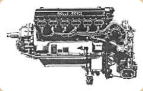
“Kestrel”
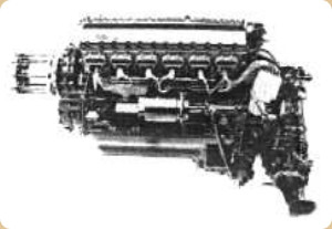
“Another Kestrel”
-In the upper picture there is a supercharged Kestrel for a metallic propeller and the lower one is for a wooden propeller.
-From the Kestrel it is known that in the first moments of the design an attempt was made to use Burt-McCollum type sliding sleeve valves, with H. Ricardo and A.J. Rowledge's involvement in the design.
-In March 1931, this model ran for the first time, and was tested with different fuels.
-Another one ran on Diesel.
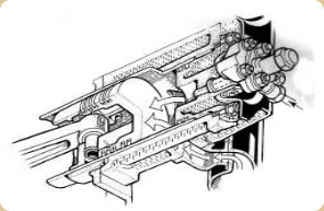
“Kestrel-Diesel system”
-None of these Kestrels flew though. One was delivered for the land speed record in the “Flying Spray” car with which two short distance records (Km and Mile) were obtained in 1936. This engine is now exhibited at the Beaulieu Museum.
-Larger than the F series were the H engines, also from 1927. These became known as the “Buzzard”, of which only 100 were made, but they were mounted on various types of aircraft.
-This engine was the basis for the “R” used for the Schneider Trophy, the Merlin and the Griffon, etc.
-The Buzzard engines that were made already reached 925 HP, since they were larger than the Kestrel as we have already said. Curiously, 40% was exported to Japan.
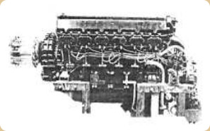
“RR, Buzzard”
-Later the Griffon would have the same stroke and piston diameter as the Buzzard. We are in 1929 and it was decided to intervene in the Schneider Trophy with an engine for the S6.
-Supermarine's S5 carried the Napier Lion, already limited by design.
-Before this we are also going to deal with the “Goshawk” from 1927. It was an F to which a steam refrigeration system was arranged, being able to raise the boiling point from 100° to 164°. Few were made, a couple of dozens.
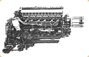
“RR, Goshawk”
-This cooling system was called “evaporative”.
-Coming back to the engine for the Supermarine S6, it was called the “R” model. And already in 1929 it was giving 1,900 HP, for the Schneider Trophy as we said before. It had to compete with the Fiat AS-14 engines (see), which was the union of two AS-6.
-A couple of years later the R already gave 2,783 HP on a test bench.
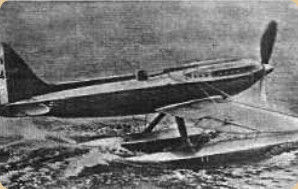
“Supermarine S6B”
-This power was obtained in 1929 using a fuel mixture consisting of 78% benzol, 22% Romanian oil and 2.5 cc per gallon of TEL (Tetraethyl Lead).
-In 1931 the “R” reached 2,350 HP and before the race, working against the clock, they were reinforcing parts such as the connecting rod system that were fork connecting rods becoming articulated. Providing dynamic intake and supercharging until the engine reached 72'3 inches Hg of MAP (Manifold Absolute Pressure).
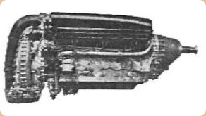
“Rolls Royce R-engine view, very aerodynamic”
-It was also necessary to change the fuel again due to so much intake pressure: 30% benzol, 60% methanol, 10% acetone and 4.2 cc/gal. of TEL.
-The rocker-box covers were lowered from the front to adjust it to the aerodynamic lines of the plane.
-By the way, the design of the S6 is due to R.J. Mitchell, who later would take care of the Spitfire.
-An attempt was made to make a V-16, but there were parts that did not resist the effort for 1,800 HP.
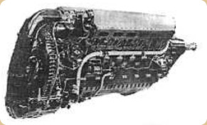
“RR, R-engine rear view”
-It is good to remember that in 1928 Henry Royce agreed to produce an engine that would power the Supermarine race plane for the 1929 Trophy.
-The Air Ministry also decided to enter just 7 months before the month of September 1929.
-It was too tight for a new design and it was decided to develop the "Buzzard" and the result was the "R-engine", with the already mentioned initial power of 1,900 BHP compared to the original Buzzard of 925 HP.
-The Supermarine seaplane won the race with this engine, with the power doubled and even more, surpassed. Without increasing its displacement and in a short time.
-After the race H. Royce was awarded a Barony.
-Later in 1931 and with an “R” of 2,300 HP, a Supermarine S6B won the Schneider Trophy permanently for the UK.
-On September 29, the speed record was 407.5 mph.
-Twenty "R" engines were made to break absolute speed records on land, sea and air.
-From the experience with the "R", the company began a particular adventure, the construction of the PV-12 or Private Venture 12 engine.
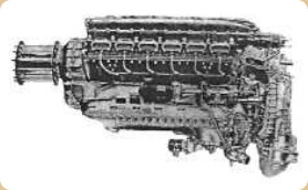
“RR, PV-12”
-The first PV-12 ran in 1933 with little power, 790 HP only but it attracted the attention of the Air Ministry that baptized it as “Merlin”. Sir Frederick Henry Royce died at this time.
-If the Kestrel had 22 liters and the "R" had 36 liters of displacement, the Merlin had 27 liters, that is, it was not much larger.
-Later it turned out to be the most famous V-12 Rolls Royce engine. A total of about 168,000 engines of all series were made.
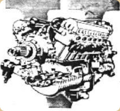
“Merlin V-12”
-The power was increasing with the B, C and F. Finally, the latter entered production as Merlin I. The Merlin G came out in 1937 as Merlin II, with 1,030 HP and 3,000 rpm.
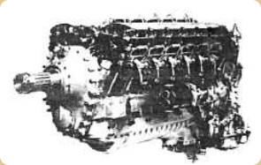
“Merlin I”
-From this moment and during WWII about 150,000 Merlins were built, the rest after the war. In Great Brittain, the Ford Motor Company intervened and in the USA, Packard and Continental.
-So many Merlin engines are difficult to classify since there were many series but we can at least relate three families for their supercharging system.
-The first thing to say is that the Merlin made many planes good, even compared to the German ones they were fighting, due to its specific power and other values. But it had a weak point in the beginning of the race and this was carburetion failure with negative Gs.
-It was partly fixed with a pressure carburetor, and being definitively solved with the injection Bendix-Stromberg at one point -in front of the supercharger impeller-.
-The Germans knew about this initial problem that they themselves did not have as they used a piston pump injection system. So to escape they only had to lever forward.
-We return to the attempt to classify the Merlins: let's say that the Merlin I had a supercharger with only one stage and one speed and that the ones mentioned below had the same:
-Merlin II, XII, 30, 45 y 46.
-With a single supercharger stage but with two speeds, there were:
-The Merlin X and XX series.
-With two-stage, two-speed supercharger and intercooler:
-The 61, 64, 66, 70, 76, 85, 100 series, 130 series and 140.
-Although this relationship is taken from an official publication, we find the 24, 25, 66 series and the same ones built in the USA as 224, 225 and 266. Also the 500/600 series. Let's try to describe them.
-First to say that the Merlin I powered the Fairey Battle I. The Merlin II and III were used on the Spitfire I, Defiant I, Hurricane I and Sea Hurricane I. It delivered 890 HP at 2,850 rpm and was geared from 0.477 to 1.
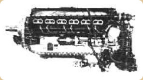
“Merlin III”
-In all Merlins, the camshafts drove four valves per cylinder and these were cooled inside with sodium, which liquefied with the temperature.
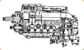
“Merlin schematic drawing”
-Because the cylinder blocks were completely facing each other, that is, not offset, the connecting rods had to be one of the fork type and the other normal. The articulated type of the “R” engine was not adopted here.
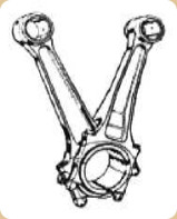
“Merlin connecting rods”
-The prototype of the Spitfire designed by Mitchell had a large wooden propeller, using one of the first Merlin engines.
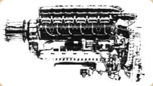
“Merlin with hub for wooden propeller”
-As a redundant comment, if, between England and the USA, 150,000 Merlin engines were made during the war, the production -with a single model- exceeded the production of other factories such as Bristol, which since 1936 made 101,200 engines in total, Napier made about 6,000 of its Saber model, or Armstrong Siddeley that made about 35,000 engines of the Cheetah model.
-So you can see the importance of the Merlin engine and of Rolls Royce itself.
-The Merlin VIII gave 1,080 HP at 3,000 rpm, but with gasoline of 100 N.O. power went up to 1,275 HP, on the Fulmar I.
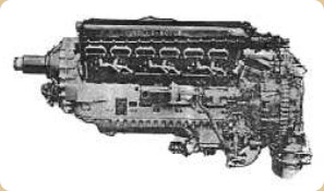
“Merlin X”
-The Merlin X, with a two-speed supercharger, gave 1075 HP but with the ability to maintain power at high altitudes.
-The X-engines powered the Halifax I, Wellington II, Whitley V and VII planes.
-The Merlin XII/30 series were simple, with a one-stage, one-speed supercharger. The 30 series were mounted on the Spitfire II. It gave 1,175 HP at 3,000 rpm.
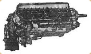
“Merlin XII = Merlin 32”
-We will also see this same simple supercharging system in the 45/46 series since we are following the numerical order of the Merlins.
-The XX model is the last to use Roman numerals. It gave 1,280 HP and was mounted on the Beaufighter II, Defiant II, Halifax II and V, Hurricane II and IV, Lancaster I and III.
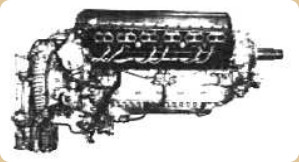
“Merlin XX”
-As previously stated, the Merlin XX had a single compressor with two speeds. Interestingly, all Merlins had a 6:1 compression.
-The V formed by the cylinder blocks was at 60°, that is, the formed geometric angle was equal to the ignition angle and 60° x 12 cylinders was equal to 720°, or what is the same, two exact turns of the crankshaft for a 4-stroke engine.
-The Merlin 21 powered the Mosquito I, II, III, IV and VI. It gave 1,280 HP, the same as the Merlin 22 that was mounted on the Lancaster I and II, as well as the York I.
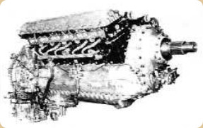
“Merlin 22”
-The Merlin 22A was manufactured by English Ford in an unknown number. But from the 22 data appears that almost 1,500 were made in Derby by Rolls Royce, 1,387 in Crewe by Rolls Royce as well as 2,164 in Glasgow. English Ford made 5,590 Model 22 engines.
-The Merlin 23 gave 1,390 HP and was installed on the above mentioned “Mosquitoes” in addition to the XII and XIII.
-The model 24 with 1,610 HP was similar to the XX and 22 but with the “anti-G” carburetor designed by the Royal Aircraft Establishment (RAE). The T-24 version (-1 and -2) that was similar to the 24 but for long life. It was the predecessor of the civilian “500” series. See further below.
-The T-24-4 would give rise to the civilian Model 501 series. The -4 was manufactured between 1944-45.
-The Merlin 25 with even more power, 1,620 HP, was mounted on the Mosquito VI and XIX.
-The Merlin 28 and 29 were built by Packard in the USA, with designation V-1650-1 (see).
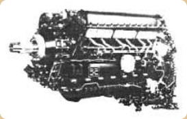
“Merlin-Packard V-1650-1”
-The 29 had a splined propeller shaft according to US SAE W50 specification. It was mounted on American Mustang aircraft and those made in Canada.
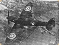
“Spitfire with Merlin engine”
-Entering the "30" series, the 30 and 31 gave 1,300 HP. The 30 was intended for the Barracuda I and the Fulmar II. The 31 was also manufactured by Packard in the USA as V-1650-1.
-The Spitfires were identified by the shape of their elliptical wing. With this plane and thanks to its engine, Great Britain had an exceptional machine for the contest that was coming and that had a crucial moment in the Battle of Britain. Merit of pilots, aircraft and engine.
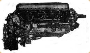
“Merlin 32”
-The Merlin 32 in the illustration above gave 1,600 HP. The Merlin 33 and 38 delivered 1,390 HP and were also made by Packard (and Continental).
-Coming to the 45/46 series, the 45 powered the Spitfire V, P, R, IV and VII, as well as the Seafire II. It gave 1185 HP.
-Here is another way to follow the evolution of the Spitfire plane. Its powers and engines could be identified by its propellers: The prototype had a two-blade wooden propeller. In 1939 it used a 3-blade propeller, and in 1941 it was 4-blade one. In 1943 the one with 5 blades came out, and in 1945 there was a Spitfire with contra-rotating propellers (Griffon engine) with six blades all together, 3 + 3.
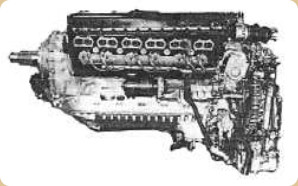
“Merlin 45/46”
-The 46 lowered the power to 1,100 HP. The same for the 47 that was used on the Spitfire VI with a pressurized cabin.
-The engines of the 50 series were identical to the 45, and were installed on the series of Spitfires and Seafires that followed.
-With the “60” series, the highest performance engines began, with a two-stage, two-speed supercharger and, above all, with an intercooler.
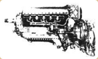
“Merlin 60”
-The Merlin 60 with 1.165 hp for the Wellington VI was postponed. The box at the upper rear is the intercooler to cool the mixture before it enters the cylinders. The engine is somewhat longer.
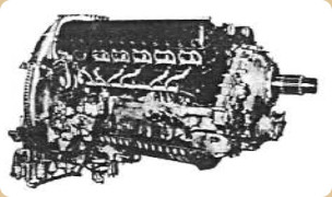
“Merlin 61”
-We see the tremendously compact 61. It delivered 1,290 HP at 3,000 rpm. (Interestingly like the compression ratio -6:1- the maximum revolutions of the crankshaft were established at 3,000 rpm).
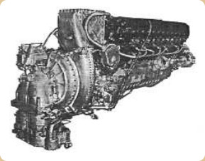
“Merlin 61, rear view”
-To the Author, this photograph of the Merlin 61 may be one of the most beautiful ever made of an aviation engine, along with the Hispano Suiza V12 that is also mentioned in its chapter (see).
-The 61 powered the Spitfire VII, VIII, IX, PR and XI. The next one, the 62 for the Wellington VI, was obsolete. The 63 was alternated with the 61 on the same aircraft.
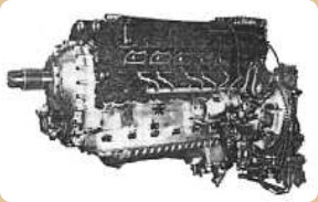
“Merlin 61, left side view”
-The 64 was for the Spitfire VII and pressured the cabin as well. It gave 1,290 HP.
-The 66 with 1,315 HP was mounted on the Spitfire LF, VIII and IX.
-All two speed supercharged engines gave a little more power at altitude, for example the 65 went from 1,315 to 1,650 HP at almost 24,000 feet.
-For the Lancaster B Mk1, only 2 engines were made in 1943.
-Remember here that apart from H. Royce, who gave the guidelines and had already died, the designers for the Merlin engines were more specifically the engineers A.G. Elliot, E.W. Hives and A.J. Rowledge.
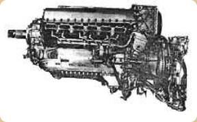
“Merlin 66”
-In most of the photographs we see the BTH magnetos on both sides at the rear of the engine.
-And in the earlier showed XX and 22 engines, we see the oil pressure regulating valves to divide the pressure into two values according to the use for the propeller, lubrication, etc. In the other photographs it is covered by electrical accessories.
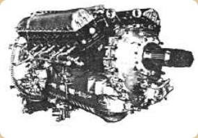
“Merlin 66”
-The 67 had identical characteristics to the 66. And the 68 was the Packard V-1650-3 that powered the Mustang III, the P-51B and C.
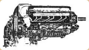
“Packard-Merlin V-1650-3”
-Mustang fighter and escort aircraft turned out to be more effective with English-designed engines than with American ones. It was a famous duet that of Packard-Merlin or Merlin-Packard in Mustang. With 1,400 HP and 1,650 HP at altitude.
-The Merlin 68 is listed as similar to the 66 and was basically the version of the Merlin 85 built by Packard for the Lincoln B MkII. The 68A was similar.
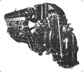
“Merlin 69”
-The Merlin 69 was also manufactured by Packard as V-1650-7 with the same powers as the -3. It was used on the Mustang III and IV (P-51C, D, F and K).
-The 70 and 71 series with 1,250 HP were mounted on Spitfires. The 72 and 73 with 1,290 HP powered the “Mosquito”.
-The 76 and 77 like the 72 and 73 were prepared to pressurize the cabin, and had a power drop to 1,250 HP on the Mosquitoes.
-The 1,635 HP Merlin-85 was similar to the 66 and 68 and was intended for the Lancaster VI and Lincoln I. The 86 was similar to the 85 and was planned for the Lincoln B MkII and Lincolnian.
-We now turn to the “100” series that was initially intended for the Mosquitoes. The 102 was experimental and reinforced for civilian use. 169 engines were made at the Glasgow factory between 1944 and 1946.
-The 102A was like the previous one with the same 1,635 HP, and was intended for the Lancastrian.
-The 113/114 are shown below in photography and schematic drawing so we can see the two supercharger stages and the multiplier gears as well as the clutch levers.
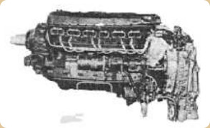
“Merlin 113/114”
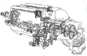
“Merlin 113/114, schematic drawing”
-The coolant used on the Merlins was a mixture of water-alcohol, that is, glycol. (80% water and 20% alcohol, plus a corrosion inhibitor).
-Regarding the multiplication of the superchargers, we have two speeds: the first one from 6.39 to 1 and the second one from 8.03 to 1.
-The Merlins 130/131 were mounted on Hornets. Specifically the 130, gave 2,030 HP.
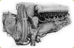
“Merlin 130”
-They continue with the two-speed, double compressor and heat exchanger, which results in a good "backpack" behind the engine itself.
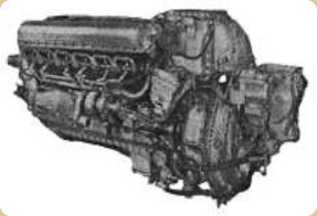
“Merlin 130/131”
-Next we see the sectional drawing of the reduction gear for the propeller and front accessory box. We can see the half hidden sprocket at the end of the crankshaft, an intermediary one, and the drive for the propeller. They were also destined for the Mosquito. There was the possibility of RH and LH propeller rotation.
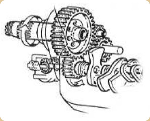
“Normal reduction gear”
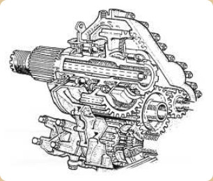
“Reduction gear for inverted rotation”
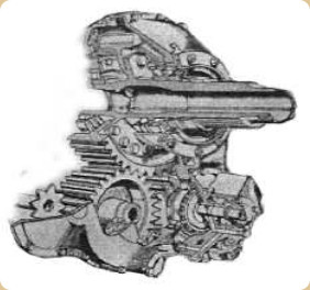
Reduction gear, front view”
-The intermediary to change the propeller rotation can be seen clearly in the above diagram. In both, 113/114 and 130/131, the reduction was from 0.420 to 1.
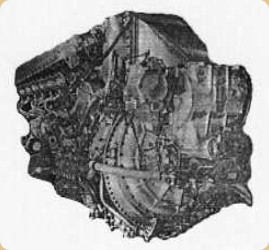
“Merlin 130/133”
-The 130/133 is photographed where it is most impressive. Next we deal with the Merlin 140. It was the link to the Griffon. With double contra-rotating propellers, this engine was the only Merlin model with this device.
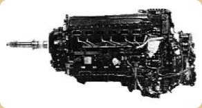
“Merlin 140”
-By the way, the propellers used to be DeHavilland or Rotol hydromatic on the British fighter planes of the time.
-Packard still followed with the 224, 225 and 266 models, which were the same as the 24, 25 and 66, respectively.
-After the war, Rolls Royce continued production and export. Both for civil and military aviation.
-For example, Italy received the 500/20 that were mounted mainly on the Fiat G59, at the Italian Aeronautic Service. They gave 1,635 HP of maximum power. The 500 were derivatives of the T-24/2 (see at the beginning of Merlin).
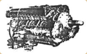
“Merlin 500/24”
-The 500/45 have been used in Spain on the Hispano “Buchón”, which was a version of the German Me109. On the Casa-Heinkel 2111, Merlin 500/29 engines were mounted.
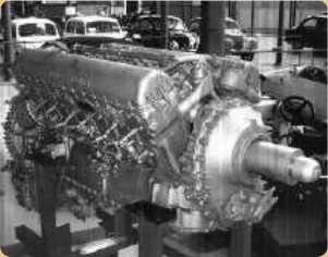
“Merlin 500/29”
-The Merlin 500/29 in the photograph is exhibited at the Museum of Science and Technology in Terrassa, in the province of Barcelona.
-It is indicated that it was a donation from the widow of the Rolls Royce Aviation representative in Spain, Olabour SA.
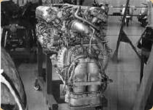
“The same 500/29, from behind”
-In this second photograph we see the carburetor and the conch of the one-stage compressor. It doesn't have an intercooler.
-The 501, with 1660 HP, was derived from the T-24/4, with a two-stage, one-speed supercharger an "after-heater" to prevent spark plug fouling. They were intended for the Lancastrian I aircraft, and were manufactured between 1947-49.
-Taking advantage of the war inertia and the great experience obtained, some civil aircraft used these engines. Thus Canadair's Douglas DC-4M was powered by the 620.
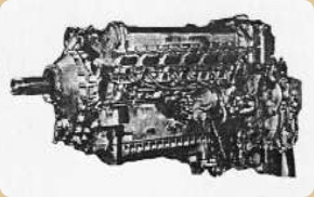
“Merlin 620”
-The 1770 HP 604 was rare. It was a military version of the civil 621, and was mounted on the Lincoln B2 for Argentina. It was produced between the years 1947-49.
-Before finishing with the Merlin model, let's go through curiosities of this engine. For superior fighters the "H" was developed with cylinders precisely in vertical H and two crankshafts (system seen in Hispano Suiza, Napier, Breguet-Bugatti, etc.). It gave 3,500-4,000 HP and it used components from the Merlin. By having four blocks of the same cylinders, the displacement rose to exactly 27 x 2 = 54 liters.
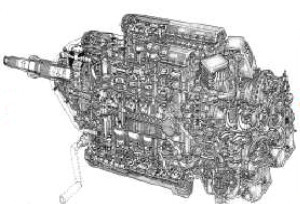
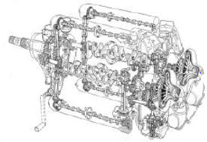
“Merlin H, cutaway and schematic drawing”
-First we have to say that these two drawings belong to the fabulous technical artist, Mr. Lyndon Jones. Featured in a Rolls Royce Heritage publication.
-They are shown here to get to know this rare engine, unknown to almost everyone.
-The study of it began in 1940 and its design ended in 1942, but it did not prosper.
-The Merlins were used for marine and terrestrial use.
-So the RAF had some boats for the rescue of overboard fallen crew members. These boats were powered by Merlin engines, becoming known as Sea-Merlin.
-The RAF rescue service was the A.R.S. or Air Rescue Service.
-Alternating its mounting with the Napier Sea-Lion and others, on the various life-boats.
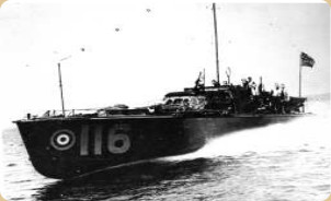
“RAF rescue boat”
-As we can see, the carburetor intake goes up and the output of the transmission is direct, surely towards reduction and reverse gear.
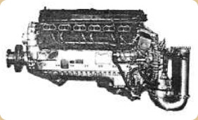
“Sea-Merlin”
-Regarding its terrestrial use, the most powerful engine up to then for tanks was the 350 HP Librerty, but of an outdated design and with certain limitations.
-So after some research by Rolls Royce, without a supercharger and without other modifications, the new Merlin could be adapted in the same space as the Liberty.
-The new Merlin gave 600 HP, which was almost double the tank engine available until then.
-Renamed “Meteor”, it was first installed on the Cronwell tank (a development of the Crusader tank). Rover also made them.
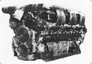
“RR, Meteor”
-The next aero engine that we will deal with is the "Griffon". It is larger than the Merlin, it had a displacement of 36.7 liters.
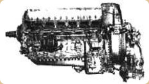
“RR, Griffon”
-The model 61 can be considered as the basic design but there were many others. Studies began in 1938 and the prototype was produced and tested on Henley and Battle aircraft.
-Due to the war, all efforts were concentrated on the Rolls Royce Merlin and it was not until the end of 1942 that the Griffon II was ready for production.
-It had a dual two-speed supercharger and an intercooler. The powers were above 2,000 HP.
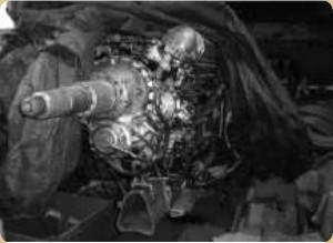
“Griffon in Mataró”
-The collector of aviation engines and other wonderful machines, Col. "Enginys Mecanics" from Mataró (Barcelona province) owns this Griffon of a Shackleton maritime surveillance plane.
-The first military application of the Griffon II was on the Spitfire F VIII. There were only two squadrons operating this engine, but they were enough to demonstrate the Griffon's potential for further development, which was seen in the Fairey Firefly.
-The Griffon IIb was mounted on the Spitfire Mk IV and F Mk20.
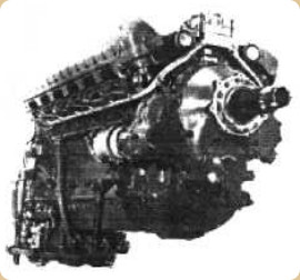
“Griffon IIb”
-It had a single two-speed supercharger and transmission shaft for a propeller. It was from the year 1942. The Griffon III that was similar to the one mentioned before was mounted on the Spitfire Mk XII. 101 engines of this model were made in the Derby factory. The IV had reduction gear with a ratio of 0'510:1. The III and IV started with 1,750 HP.
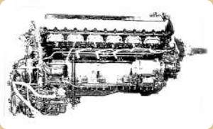
“Griffon IV”
-The Griffon VI was intended for the Seafire Mk XV, VXII, and the Spitfire XII and XVIII. In Derby 860 Griffon VI engines were made between 1944 and 1945. They delivered 1,890 HP.
-The Griffon 26 was like the MkIII with a 0`4423:1 reduction. The Griffon 35 ML had a 3-speed supercharger and fuel injection.
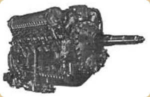
“Griffon 57 for contra-rotating propellers”
-The 57 that gave 2,450 HP, used contra-rotating propellers and was installed on the Supermarine Seagull.
The 61 was mounted on the Spitfire Mk XIV, F Mk 21, 22, 23 and 24 as well as the Seafire Mk 45, 46 and 47.
-The Griffon 62 was similar to the 61 but with fuel injection using 115/150 O.N.. gasoline.
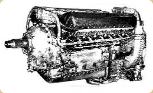
“Griffon 60 series”
-The 64 was very similar to the previous ones and to the 69, which had a Bendix/Stromberg injection carburetor. About 200 units were made at the Crewe factory.
-The 65, like the 61, had a triple venturi carburetor and reduction gear for the propeller like the IV.
-They were mounted on the Spitfire XIV, XVIII and Mk XIX. Nearly 1,500 of these engines were made between the Crewe and Derby factories.
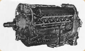
“Griffon 65”
-The 65 gave 2,220 HP at 2,750 rpm with 12 glycol-cooled cylinders in V. It was capable of ascending to 40,000 feet, counting therefore with two-stage, two-speed superchargers and inter-cooler radiator or heat exchanger.
-The Griffon 66 was intended for airplanes with a pressurized cabin. In 1945, 200 engines were made. The 67 was like the 65 and 69, giving 2,375 HP at 2,750 rpm.
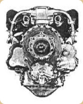
“Griffon 65, front view”
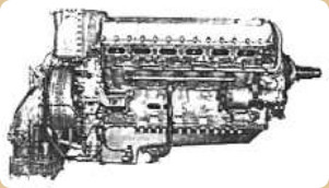
“Griffon 67”
-The 69 was based on the 64 with a modified crankcase and a Bendix/Stromberg injection carburetor.
-The 83, 85, 86, 87, 88, 89 and 90 were similar, and all of them had coaxial shafts for the contra-rotating propellers. They were mounted on Spitfires and Seafires, except 89 which was installed on the Seafang Mk32.
-The Griffon 101 had a two-stage, three-speed supercharger. It gave 2,440 HP and single puller propeller. It was mounted on the Spitfire XIV and Seafang Mk16.
-Production was carried out in 1945. It was similar to the 121. The 102 was similar to the 101 but with two contra-rotating propellers, and was intended for the Spitfire 21 and the Spiteful. The 105 was also similar.
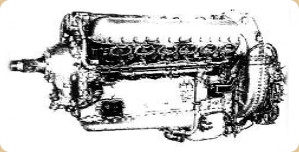
“Griffon 101”
-The 121, with contra-rotating propellers powered the Shackleton MR2. But they were also mounted on the Spitfire F Mk21.
-The 122 was based on the 101 but it had coaxial propellers. They powered Spitfires and Seafires. Griffon models up to 130 appeared.
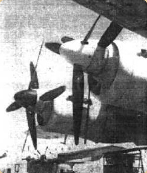
“Appearance on the Avro Shackleton”
-Now we are going to treat the “Peregrine”. It was a descendant from the Kestrel, taking advantage of the experiences with the Merlin engine.
-In 1940, the Peregrine was installed on twin-engined Whirlwind fighters with certain flap configurations. Having the radiator inlets on the leading edges of the wings it had problems with overheating. It had no continuity.
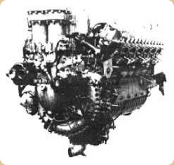
“Peregrine”
-Now we have derivatives from the Kestrel and from the Peregrine. They made the "Vulture" using many parts from the above mentioned engines.
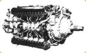
“Vulture, right front view”
-It used all four cylinder blocks from the Peregrine and they were arranged in X-24. The engine's design started in September 1938 and it was tested in 1939.
-It gave 1,800 HP, but to avoid problems the maximum revolutions were successively reduced, from 3200 to 3000 and finally 2850 rpm.
-As a coolant, it used 70% water and 30% ethylene-glycol. It had a single-stage, two-speed supercharger. It was the Vulture I, running on 87 Oct gasoline.
-The Vulture II was an upgrade of the previous one to use 100 Oct gasoline.
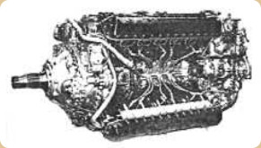
“Vulture, left front view”
-It was produced between 1940 and 1942, and was mounted on the Manchester planes of the 97 Squadron. But the constant problems made them jokingly refer to the "97th Infantry".
-Nine Vulture V engines were tested on Tornado aircraft.
-The production base for frame makers was the Merlin, and eventually the Griffon. But Rolls Royce did not stop looking for ways to obtain higher powers.
-Now we come to the “Exe” engines (also known as “Boreas”).
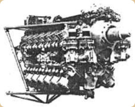
“Rolls Royce, Exe or Boreas”
-Studies began in the 1930's but the project was abandoned in 1940 in favor of the Merlin and Griffon.
-The Exe had 24 cylinders in X like the Vulture but the difference was that it was air-cooled and the cylinders were valveless, that is, with sliding sleeves. So in vogue at this time. There were problems with the gearbox.
-The "Crecy" was another interesting engine. Originally known as P-1. It was proposed and developed by Sir Harry Ricardo, with construction details from the Griffon. It is mentioned that a few test engines were built.
-They had a mechanical supercharger and at least three exhaust-driven turbochargers. They were 12-cylinder in 90°-V two-stroke engines.
-They delivered 1,800 HP at 2,750 rpm with reduction gear. The injection pumps (Diesel) are at the front, above the gearbox, 45° inclined and feeding each line of cylinders.
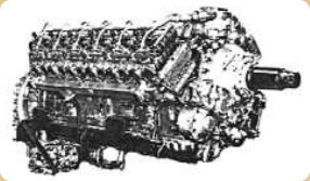
“RR, Crecy”
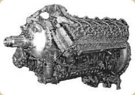
“Crecy, from the other side”
-Although it gave good power-weight ratios and low consumption, it overheated, especially the pistons, which made it give up on its development, around 1945.
-With a mechanical supercharger, 2,000 HP was stipulated, being able to reach 3,000 HP with a turbocharger.
-The “Eagle” (third Rolls-Royce engine with this name) started in 1942. It was like a Napier Saber but enlarged and for contra-rotating propellers.
-The cylinder layout was a horizontal H-24. It had two crankshafts and with a sliding sleeve device. In fact it was like coupling two horizontally-opposed cylinder engines, one on top of the other.
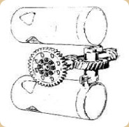
“Sliding sleeve device”
-The new Eagle in its Mk22 version gave 3,500 HP. On the Wyvern it was limited to 2,690 HP.
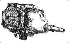
“Eagle 22”
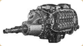
“Eagle, from the other side”
-It seems that, as we have seen, all Rolls Royce piston engines used bird names. Not finding a suitable one for the engine, the Eagle was repeated.
-The engine was liquid-cooled. It had a two-speed, two-stage supercharger. Fuel injection was carried out - as in the Merlin and Griffon - by a nozzle just in front of the supercharger wheel.
-It had coaxial shafts and counter-rotating propellers. This was the most powerful engine of the brand at the time.
-Although the one with the most displacement (45.76 liters) of RR was the next one, the “Pennine”, with 24 cylinders in X.
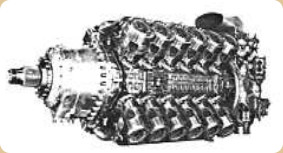
“RR, Pennine”
-It was air cooled, with the same idea as the Exe. The use of a large epicyclic gearbox did not cause the problems that the Exe had. Planned for 3,000 HP it gave 2,750 HP at 3,500 rpm. The cylinders had sliding sleeves.
-The efforts to achieve greater piston power would end here, since Rolls-Royce had already begun to study turbines in 1938, the necessary power would be obtained with those engines.
-But before closing the piston engine part, it should be noted that in the 1960's the brand again built engines for light aviation, under license from Continental.
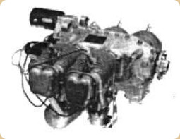
“RR-Cont. 0-200”
-Initially the O-200 and O-300 that would be installed on Cessnas that were assembled in Reims (France), followed by the IO-360 and a derivative that was made by Rolls-Royce, with two cylinders less than the latter, the O-240.
-The IO-368 had no known application, but with four cylinders it covered what was achieved with six in the Continental IO-360, giving 180 HP.
-The 100 HP O-200 would be mounted on the Cessnas F-150 and the Socata-Rallye. The O-240 model, with 130 HP on the Cessnas FA-150 Aerobat, from Reims. (Ex Max Holste factory).
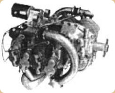
“RR-Cont. O-240”
-The O-300 was installed on different Cessnas F-172 that emerged from Reims.
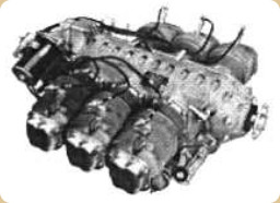
“RR-Cont. O-300”
-The O-300 gave 145 HP, simple, classic, easy to maintain and with six cylinders. Like all Continentals, the rockers were “0 adjustment”, that is, with hydraulic lifters.
-The O-240 used the same cylinders as the IO-360. But it had a carburetor while the latter was injected, with continuous flow typical of Continental. The IO-360 gave 210 HP.
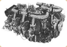
“RR-Cont. IO-360”
-The entire production line manufactured by Continental was done at the Crewe factory.
-The IO-360 engines were on the Cessnas Reims Rocket or FR-172, the XP and the practical "Push-Pull", the Cessna F-337, with two engines on the same shaft, one for pulling and the other for pushing. The military “Milirole” is included.
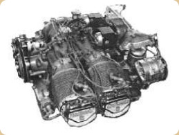
“RR-Cont. IO-368”
-Taking the thread of the first turbine studies in 1938, and when Dr. Griffiths joined the company in 1939, several experiences were carried out that Griffiths himself proposed in 1929, it was the CR-1 engine.
-Rolls-Royce gained a lot of compressor experience by supercharging piston engines.
-This, together with the encouragement received from learning about the Gloster E28/39's flight with Whittle W1 engines in May 1941 and later with the W1A, led to the construction of the WR1 in early 1942 under an agreement with Power Jets. The WR1 was based on the W2B (made by Rover).
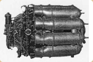
“RR, Welland”
-But incorporating ideas from RR, coming to assume the responsibility by subcontracting Power Jets, to procure the power for the Gloster Meteor in 1943, with the “Welland” engine.
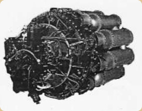
“RR, Welland”
-The Welland was based more specifically on the W2B/23 with 1,400 lbf of thrust, but with the Welland (RB23) it was increased to 2,000 lbf.
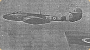
“Meteor with Welland”
-Thus, the W2B/23 were the first engines capable of improving the No. 616 Squadron RAF, with the Gloster Meteor.
-Curiously we have seen that Rolls-Royce named their piston engines after birds. For the turbine engines it uses names of English rivers. We will see that many engines use the initials “RB”, they are from Rolls-Royce Barnoldswick, Design Bureau.
-In the early days, as we will see, some letters were added to these commercial names of rivers that indicated, in addition to the internal RBs, the following:
-RD, for RR Derwent.
-RN, for RR Nene.
-RDa, for RR Dart.
-RTy, for RR Tyne.
-RA, for RR Avon.
-RCo, for RR Conway.
-RTa, for RR Tay. Etc. As we will see.
-We take advantage here to mention a caveat. There was an RA.660 engine that was not an Avon but was for control of the VTOL aircraft, HS-810.
-We continue with the W2B/26 project at Rolls Royce with the RB.26 and the RB.37 that was called the “Derwent”.
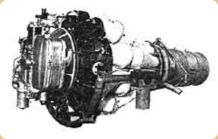
“RR, Derwent I”
-The Derwent I appears in 1943, with 908 Kgf of thrust. It was installed on the Meteor III.
-The Derwent II is from 1944, initially with 1,000 Kgf of thrust. In the same year it went to 1,090 Kgf of thrust. And in 1945, the IV started with 1,070 Kgf of thrust.
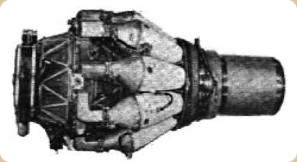
“Derwent V”
-From then on the Derwent V was already commercially the RD.7, with 1,590 Kgf of thrust for the Meteor V. In 1950, the Derwent VIII (RD.7) gave 1,630 Kgf of thrust.
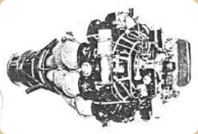
“RR Derwent V, RD.7”
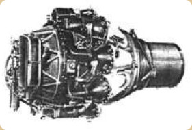
“Derwent RD.8”
-The RD.8 engine went up to 1,900 Kgf. The RD.9 gave 1720 kgf. The RD.10 with 2,270 Kgf and the RD.11 gave 2,040 Kgf of thrust.
-The RB.39 project was a turboprop whose first works began during WWII.
-It had the hot zone of the Derwent but it was reinforced for the increased pressure ratio (Pr).
-A large axial compressor was added previously. With a front reduction the engine increased its size to almost double. This was the "Clyde".
-It is said that the axial compressor came from a Metrovick F2 and the centrifugal part from a Merlin piston engine supercharger. As it was, it ran in 1945 giving 2,000 SHP, with the -9 design it reached 4,500 SHP.
-Generally, the initial turboprops gave a power to the shaft plus a residual thrust, which due to lack of good use in the turbines was important and countable.
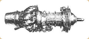
“RR, Clyde”
-In 1944, the RB.40 project with 1,900 Kgf of thrust, was the embryo of the RR “Nene”, which was the RB.41 project that followed.
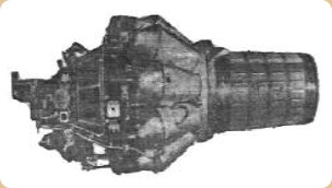
“RR, Nene”
-The Nene were larger than the Derwent, starting their nominal thrust in the 2,000s and reaching up to 2,700 Kgf of thrust.
-All the first Nene engines were RN.2 commercially.
-Except Nene 1, which was RN.1, the following Nene-2, -3, -4, -5 and -6 were RN.2.
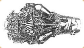
“Nene cutaway”
-Generally it was similar to the Derwent, it had separate, individual combustion chambers, but joined by small interconnection tubes, which balanced the pressures between them and at startup also spread the flame between them. The centrifugal compressor had a double-sided impeller.
-And as we can see in the cutaway turbine, another small compressor with an active chamber, on the same shaft, was used for internal refrigeration.
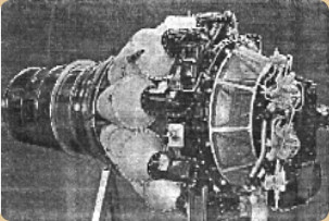
“RR, Nene”
-Great Britain provided the countries that were its allies with the jet engines that it already manufactured, and were operational, especially the Nene.
-So France was able to build it under license at Hispano Suiza as Nene-101 (RN.2) of 2,270 Kgf.
-The Nene-102 (RN.2) gave 2,320 Kgf of thrust, and in 1948 the RN.3 delivered 2,500 Kgf of thrust.
-Hispano Suiza "squeezed" the Nene, subsequently releasing the Nene-102BR that gave 3,090 Kgf with afterburner.
-The Nene-104, the -104BR, the -105A and 105AR followed to start the construction of the R-300 in 1953. (see Hispano Suiza).
-The North Americans were given the license to build it by Pratt & Whitney as J-42, in versions P-2, P-4 and P-6. All thrusts were around 2,270 Kgf.
-A batch was sold to the USSR and manufacturer Chelomey made them as M-45A of 2,500 Kgf and M-45B of 2,700 Kgf.
-And Klimov also manufactured it as VK-1 and VK-2 respectively (RD-45 and RD-45A).
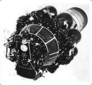
“RR, Nene”
-In 1952, Commonwealth Aircraft, manufactured it with 2,270 Kgf of thrust.
-The Nene-10 was made in Montreal, Canada, for the T-33N of this country.
-It was also manufactured by China as WP-5 but with the help of the Soviets who had manufactured it without a license and taking advantage of the act of good faith of the delivery by the British, despite the cold war.
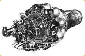
“RR, Nene-10”
-The “Tay” was a development of the Nene, known as the RB.44 project. The air flow was redesigned for 115 lbf per second and it was prepared to give 6,250 lbf of thrust. In 1951 the RTa-1 ran in the UK, giving 2,840 Kgf of thrust.
Note: the RB.43 project was a precursor to the Soar expendable engine (see).
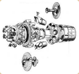
“Tay, exploded view”
-Hispano Suiza manufactured it as Tay-250A and R, with 2,840 Kgf and 3,860 Kgf respectively, the latter being with afterburner.
-The French derivative of the Tay was the Verdon-253 A-450 giving 3,500 Kgf and the R-450R, also called Verdon, reached 4,500 Kgf. They were from the year 1953. (see Hispano Suiza).
-In the USA the "Tay" was the J-48 manufactured under license by Pratt & Whitney as J-48-P4, -P5, -P6 and -P8.
-We should mention Griffith's work within Rolls-Royce, since after the CR-1 based on his patents, he was commissioned for a range of small engines that became known as AJ.
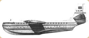
“S.Roe Princess”
-Later he made the AJ.25, which was a larger engine, the one known as “Tweed” (also known as AP.25) of 2,500 SHP. It was intended for the large Saunders Roe SR.45 “Princess” seaplane, which was to have 12 engines coupled in pairs, leaving only 6 contra-rotating double propellers.
-It was going to be the English counterpart of the Howard Hughes “Spruce Goose” that was still a bit larger.
-It turned out that the engines were not finished on time and 10 Bristol Protheus of 3,880 SHP were installed.
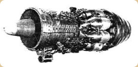
“RR, AJ-65 = RA.1”
-The AJ.50 gave 2,270 kgf of thrust. The AJ.60 delivered 2,730 kgf of thrust. In 1945, the AJ.65 would be baptized with the name of the river "Avon" with reference RA.1.
-If the other models had 8 or 10 compressor stages, the RA.1 had 12.
-The Avons started with 3,000 Kgf of thrust in 1945 and ten years later, in 1955, they already gave 5,000 Kgf of thrust.
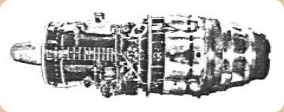
“RR, Avon RA.1”
-In 1945 they started with the RA.1 and in 1955 they went for the RA.29. There were two main lines, the “civilian” and the “military”.
-The RA.2 is from 1947 and delivered 2,730 Kgf. The Avon-100 or RA.3, is from 1948 and gave 2,980 Kgf of thrust.
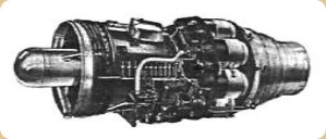
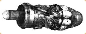
“Two RA.7 Avon engines”
-The Avon RA.7 would be the last of the 100 series that started with the RA.3. The RA.9, RA.14, RA-16, RA.21, RA.22, RA.24, RA.25, RA.26, RA.28 and RA.29 followed.
-The 200 series would start with the RA.14 from 1953, giving more thrust and using less fuel. The combustion chambers would change from separate to annular-cannular.
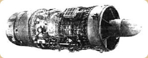
“RR, Avon 300 series, without nozzle”
-As we will see, the derivatives of the 300 series would be the RB.146. The division into civil and military engines made the Avons very popular for airplanes of the 50's and 60's.
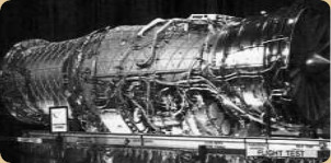
“Civil Avon”
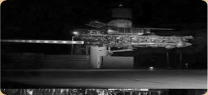
“Military Avon”
-We would see the civil Avons on the Caravelle, Comet, BAC One-Eleven, etc.
-The military ones went on the Hunter, Canberra, Lightning, etc.
-The list of both, civil and military is much more extensive.
-The RB.77 project is an attempt to replace the Avons with a 7,500 lbf by-pass turbine. Although it did not receive any name.
-The RB.50 project referred to the first “Trent” engine (later there would be two more RR engines with this name).
-It was an attempt to take advantage of the Derwent II for a turboprop. It got to fly on a Gloster Meteor.
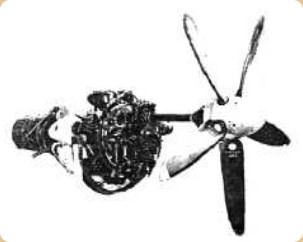
“RR, first Trent”
-The five-bladed propeller was a Rotol. It gave 750 SHP of power plus 1,250 lbf of thrust.
-We recovered a new illustration of the year 1950 in the Spanish Aeronautical Magazine.
-This is the “Trent” engine, those mounted on the first Gloster Meteors.
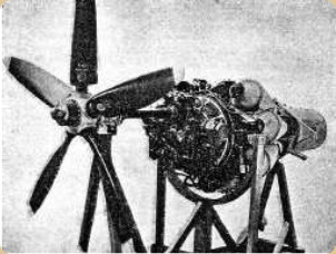
“Trent”
-As we know from the above text, there have been three families of Rolls Royce Trent engines: the one shown, an intermediate by-pass, and the one with the huge Fan capable of reaching 100,000 lbf of thrust for aircraft like the A-380.
-The one shown was based on the Derwent.
-Now the Nene is presented with split exhaust pipes for the first jet planes of the British Navy.
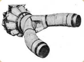
“Nene with bifurcated outlets”
-In the following design we see that the inlet is also bifurcated, which was common at the time.
-Due to the use of centrifugal compressors, the Ram effect was not as decisive as in axial compressor engines.
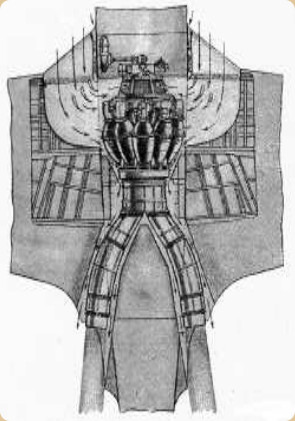
“Nene mounted on Hawker P-1040”
-Parallel axial motors were immediately installed to improve performance.
-Together with the Avon, another great success of RR was the “Dart”. Project RB.53.
-It is a multipurpose turboprop that has survived until today, in the Fokker 27 for example.
-Although a fortunate installation was in the first commercial four-engine turboprop aircraft, the Vickers Viscount.
-It had separate combustion chambers, with technology from the year 1947 when it made its first flight.
-The power jump between models was huge. It started with 1,400 SHP and went up to 3,245 SHP.
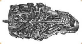
“Dart cutaway”
-The RDa.6 with 1,600 SHP and the RDa.7 with 1,800 SHP.
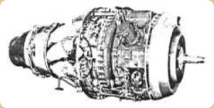
“RR, Dart RDa.7”
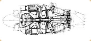
“Dart schematic drawing”
-The main characteristic of the Dart was having two centrifugal compressors with one single-sided impeller in cascade, and the combustion chambers were inclined to favor the impact on the turbine blades.
-Another characteristic, on the ground, during taxiing, there was a frontal sound of the intake, a trembling whistling, perhaps due to the flute effect of the propeller blades passing in front of the upper intake of the oil cooler. An unmistakable sound.
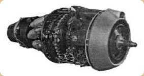
“RR, Dart RDa.10”
-The RDa.7 is the Mk529 and gave 2,020 SHP. The RDa.10 reached 3,025 SHP.
-As we see, in addition to the series, they also carry the Mark (Mk), as a form of identification. This is how we know the Mk505, Mk529, Mk536, Mk551, Mk552, etc.
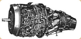
“RR, RDa Mk505”
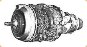
“RR, RDa Mk536”
-The RDa Dart Mk505 developed 1,400 SHP plus 165 Kgf of thrust.
-The Mk536 gives 2,80 SHP. The last versions were the Mk551 and Mk552.
-The RB.77 project was a gas turbine that was intended to replace the Avon. It was the first by-pass design by Rolls-Royce as already mentioned in the Avon section.
-Griffith's RB.78 project was a turboprop that received the designation CR.2, without further details at the moment.
-The RB.80 project was the “Conway” turbofan. The studies for this engine began in 1952. It ran the following year as RCo.2 giving 9,250 lbf.
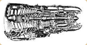
“RR, Conway, cutaway”
-The Conway is a turbojet with two shafts, the high pressure HP and the low pressure LP.
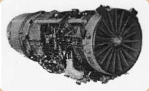
“RR, Conway”
-It was used in the military on the Victor and in civil aviation on the DC-8 and British registered Boeing 707-420 jets. They had double flow and By-pass.
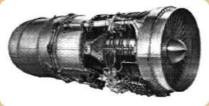
“RR, Conway”
-The RCo.11 delivered 7,830 Kgf (17,250 lbf) of thrust.
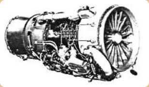
“Conway RCo.11”
-There were some series, the same as in the other engines, such as the RCo.12, until reaching the RCo.43 on the Vickers VC-10.
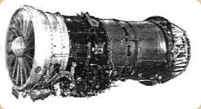
“RCo.43”
-It was the most powerful in its class with 20,370 lbf. Shown below with reverses.
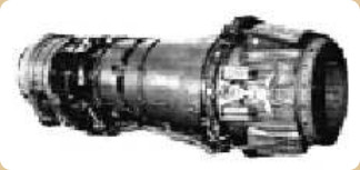
“RCo.43, reverse side”
-We now see the complete "Pod" designed by Rolls-Royce for the Boeing 707-420 that includes the rear noise suppressor, the reverse flow, the RCo.12 engine and the set of front hoods and folding sides.
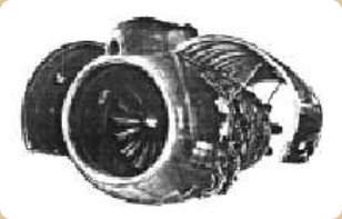
“Nice view of the Conway on B-707”
-The RB.82 was the first single-use expendable engine project for the Red Rapier missile. It became known as the Soar, with 1,375 lbf of thrust.
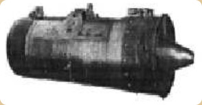
“Soar”
-The RB.90 project was going to be a further development of the Avon, without more information at the moment.
-The RB.93 project is also known as Soar, possibly an improved model since the thrust goes up to 1,750 lbf. It was also intended for the Red Rapier and for use in RPV propulsion. Extremely simple.
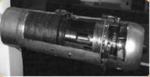
“RB.93 Soar, at the Derby Museum”
-The Soar is a small axial flow turbojet with a diameter of 40 cm and a length of 150 cm. Its power was around 840 Kgf. It flew in the Gloster Meteors reinforcing the Derwents, in tests.
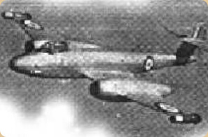
“Meteor with two Soar engines”
-Another project to expand the Avon's potential was the RB.106. At least, that it was interchangeable in the Avon nacelles. it delivered 15,000/21,750 lbf.
-The RB.108 was the number given to the project of the first lifting reactor that was made by Rolls Royce. It was installed in groups on VTOL aircraft. They had to provide the lift thrust plus the bleed to direct it to one of the "jets" or balance jets at the tips of the planes, tail and bow of the plane.
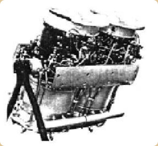
“RB.108 couple”
-In Great Britain they installed them on the Short SC.1 and in France on the Balzac. It was a complex system and difficult to control.
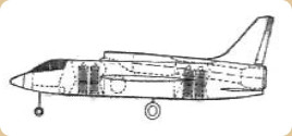
“Short SC.1 with various RB.108”
-The RB.108 gave 2,030 lbf of thrust plus 11% bleed to direct it to flight control.
-Later, Rolls-Royce would make the first jet engine that would use "composite" materials, it was in the RB.162 project, larger than the RB.108, starting with 4,400 lbf of thrust, up to 6,000 lbf.
-The engine built jointly with Allison and known as XJ-99 would increase power to 9,000 lbf.
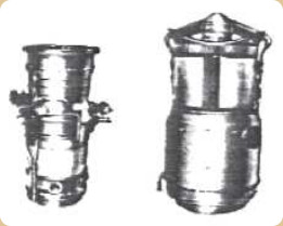
“RB.108 vs RB.162”
-Below we show a cutaway of the RR-Allison XJ-99. It was intended for vertical mounting.
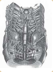
“XJ-99”
-We take advantage here to mention another engine for vertical takeoff. As Rolls-Royce received all the production of all the brands that were unified with R-R through superior orders after the war, around the 50's, and during the crises that followed.
-It turns out that from Bristol-Siddeley RR received lift turbines like the one shown below, with turbofan included, which is very interesting.
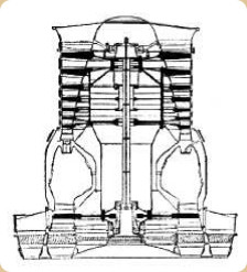
“Bristol lift-jet”
-But the solution to vertical takeoff would come in a practical way with the Bristol Pegasus, previously known as BE.53. Although Rolls-Royce followed a similar path with the "Medway" as we will see.
-Now let's see the RB.109 project, which was the “Tyne” turboprop engine.
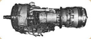
“RR, Tyne Ty.20”
-The Tyne came out with the intention of being the second generation of RR turboprops.
-The truth is that it complemented the Dart in powers from 2,500 SHP up.
-It had two shafts, the LP with a 6-stage compressor and 3-stage turbine and the HP with a 9-stage compressor and 1-stage turbine.
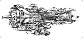
“Tyne, cutaway”
-The Tyne RTy.20 reached 6,100 SHP and there were higher powers. They were seen in the Vanguard, Canadair CL-44 and still today on the Transall, Atlantic and Aeritalia 222. There were projects to reach 8,000 SHP.
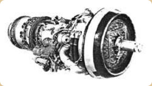
“RR, Tyne”
-To build the Tyne engines for NATO RR joined with Snecma, MTU and FN (see each one).
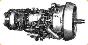
“Another RR Tyne”
-Thereafter a series of projects follows, which transcend little more than the idea of the planes for whom they should be intended. Mostly turbojets.
-The RB.115 was intended for the Bristol 188 aircraft.
-The RB.121 went to the R-156 supersonic bomber (Handley Page 100 and Vickers SP-4).
-The RB.122 was intended for the Fairey Delta III fighter plane and was an enlarged engine of the RB.106.
-The RB.123 was intended for the English Electric P10.M3 reconnaissance plane giving 10,250 lbf of thrust.
-The RB.126 with 13,400 lbf was mounted on the English Electric P8 interceptor.
-The RB.127 project was the intended engine for the R-156T. The RB.128 is a more powerful engine than the RB.122.
-The RB.133, an Avon engine repowered from the RA.24 with the intention of being mounted on the Canberra PR.9.
-The RB.140, from 1957, was a completely new-design, by-pass, turbojet engine. It did not go into production, but it led to the Medway.
-The RB.141, derived from the 8,000 lbf RB.140, went up to 13,790 lbf for the DH Trident.
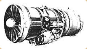
“RB.141”
-Both the 13,790 lbf RB.141 and RB.142 were for the Trident but it was also used on the HS.681 vectored thrust aircraft.
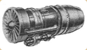
“RB.141, Medway”
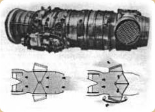
“Medway, vectored thrust”
-The vectored thrust device belongs to the RB.142 project.
-As we can see, some lids or deflectors that cover the side outlets can be moved to close the outlet through the main nozzle and open the side outlets.
-These side outlets had blinds that deflected the jets.
-This gave additional utility to the engine for S/VTOL. Of about 5,400 Kgf of thrust.
-The engines of the RB.145 project were considered light, 2,750 lbf or 1,250 Kgf of thrust.
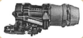
“RB.145”
-It was developed jointly with MTU, and was used in the German VJ-101C aircraft. This engine was based on the RB.108.
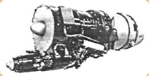
“RB.145”
-Due to the relatively small size of the engine, the size of the electric starter stands out. As well as the unusual position.
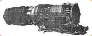
“RB.145, con P/C”
-Finally, an RB.145 with afterburner is presented, rather unclear, but it is the only picture we can show. With this engine the 2,750 lbf is raised to 3,650 lbf.
-We now turn to the RB.146 project. This is an Avon that is modified for supersonic applications.
-They were used on the English Electric Lightning, where they were superimposed one on top of the other. (Usually they go side by side in the rest of the twin-engine planes). It is also used by the SAAB Draken. It gave 17,000 lbf of thrust with afterburner.
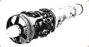
“Avon, RB.146”
-The RB.153 turbofan was a rare engine with deflected thrust. Inside the nozzle it had some unusual deflectors and adjustable side outlets. The project was canceled.
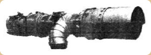
“RB.153, complete”
-These engines were manufactured jointly with the German MAN. In fact, the vectored thrust deflector was manufactured by the latter.
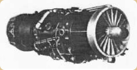
“RB.153”
-They were destined for VTOL flight projects, such as the VJ-101D, a supersonic aircraft. The modification was applied to the basic RB.153 engine. This collaboration began in 1960.
-However, it used the part of the engine that was going to inspire the Spey RB.163.
-The RB.162 was a vertical thrust engine, giving between 4,400 and 6,000 lbf. It was capable of lifting 16 times its own weight thanks to the use of lightweight composite materials.
-It was installed on flying devices or stationary flight "scaffolds", in the Dornier 31 and in the VFW-Fiat VAK 191B V/STOL.
-Its application as a "booster" engine on Trident 3B commercial aircraft is not so well known. This trijet had a Rolls Royce RB.162 booster engine just above the normal tail engine.
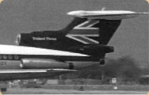
“The fourth engine on the Trident 3B's tail”
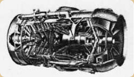
“RB.162, horizontal”
-The -86 variant is the one that allowed it to go in a horizontal position, folded 90° from its original design position, giving 5,250 lbf.
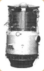
“RB.162”
-We come to the RB.163 “Spey” project, both for civil and military use.
-Made in the USA it has the military designation of F-113 and the first engine ran in 1960.
-It was used on the Trident, Bac-One-eleven, Gulfstream II and III and the Fokker F-28.
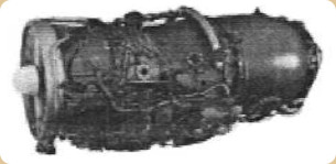
“RB.163, Spey”
-The first series were the Mk506, 511 and 512. Thrusts went up from 9,850 lbf to 12,550 lbf.
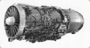
“Another RB.163, Spey”
-The designer of the Spey was F. Morley and as mentioned, it was a great success both civil and military. It was mounted on English Phantoms.
-The RB.168 were also Spey, much more powerful since they reached 20,500 lbf of thrust and versions such as the Mk202 and Mk203 were mounted on the RAF Phantoms, the Mk101 on the Buccaneer.
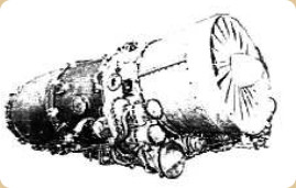
“RR Spey, RB.168-Mk807”
-The maritime patrol Nimrods were powered by the Mk250s.
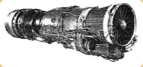
“Spey RB.168-Mk202”
-The Phantom Mk202 with afterburner (and the Mk203) reached 20,515 lbf of thrust.
-The RB.168-62, the -66 and the -68 Spey versions that were built in the USA in collaboration with Allison would be the TF-41.
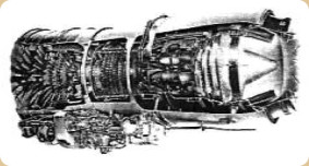
“RR-Allison TF-41”
-The TF-41 with 15,000 lbf of thrust was manufactured jointly between RR and Detroit Diesel Allison, a division of GM. It was destined for the Vought A-7 Corsair II aircraft of the US and Greek navies at the time.
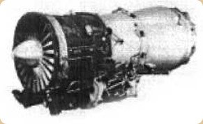
“RR-Allison, TF-41”
-The RB.172 was the first RR engine that, in conjunction with Turbomeca, was going to be used on Jaguar aircraft, for training and tactical support.
-The first version, the RB.172/T.260 gave 1,900 Kgf of thrust and with afterburner, 2,860 Kgf. Note: the Jaguar had two engines.
-Later, an evolved version of this engine would be the “Adour”. See further below.
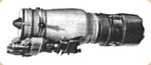
“RB.172”
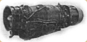
“RR-Turbomeca Adour”
-The RB.173 project was a smaller version of the Spey turbofan with a view to a Viscount turbojet aircraft. It delivered 7,500 lbf.
-The RB.175 was a turbofan lift-engine version. It was based on the RB.162 and remained a design project only.
-The RB.176 project was a lift-turbine on the Rotodyne Z, It was Tyne based, and did not go into production.
-The RB.177 was a turbofan from a modified Medway for military use. It delivered 22,000 lbf.
-The RB.178 was important for its size, for having three shafts and for supersonic transport aircraft. In 1966 a scale model was shown, running the same year although it would eventually lead to a subsonic proposal for the B-747.
-it was also targeting the Lockheed Tristar and the DeHavilland Twin-Trident.
-By its architecture, we will see that this engine was the one that initiated the outcome of the RB-207 and finally the RB-211.
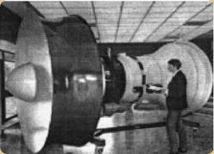
“RB.178”
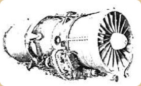
-The RB.180 was a small turbofan for a curious application: it was intended to replace the DC-3 engines. It delivered 6,250 lbf.
-The RB.183 was known as the Spey Junior, a turbofan with a high by-pass ratio. It delivered 15,100 lbf.
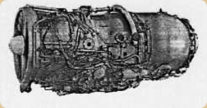
“RB.183”
“RB.183”
-It was used on the Fokker F-28. Later the -03, or rather, the RB.183 Mk555 derived into the "Tay" (second time that this name is used by RR).
-The first engine ran in 1984 and turned out to be a successful engine.
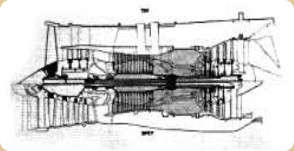
“Tay vs Spey”
-Both engines have the same "core" (dark color).
-While the Spey -lower half- is a By-pass, the Tay -upper half- is a turbofan.
-The first Tays were the 610 and 620 versions, up to the 650 and 670 in 1988 when they were installed on the DC-9, Boeing-727 and Boeing-737-200 (repowered) and delivered 18,000 lbf of thrust.
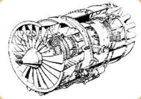
“RR Tay, cutaway”
-The Mk650 and Mk651 versions were mounted on the Fokker 100 and B727Q's.
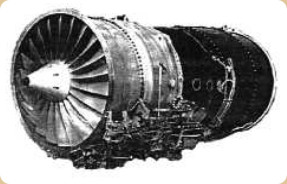
“RR Turbofan Tay”
-The RB.189 project was a lift-engine carried out jointly with Allison, the XJ-99 that gave 9,000 lbf of thrust. It was intended for use on the American advanced take-off and attack aircraft FRG. Also for the HS 1019E6.
-Now we come to the interesting RB.193 engine, received from Bristol (BS.53). This is the one that would receive the name of Pegasus used on the S/VTOL Harrier fighters.
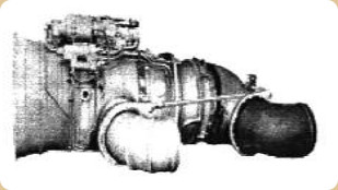
“RB.193”
-This engine was manufactured in collaboration with MAN-Turbo Unión.
-As we said, it was similar to the Bristol-Pegasus that was already in the hands of Rolls-Royce. It was a turbofan with four adjustable outlets in the 10,000 lbf range.
-It was also intended for the German VAK-191B, but this was canceled.
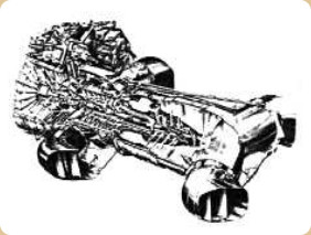
“Cutaway with nozzles”
-The vectored RB.193 was a more advanced product from the vectored RB.153, made in collaboration with MAN, that we saw earlier.
-It is currently offered in 11-61 and 11-21 versions for the Harrier II and AV-88.
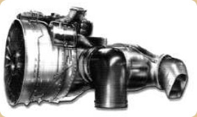
“New Pegasus 11-”
-The thrust of these latest engines already reaches 23,800 lbf. (-61).
-Another important engine is the RB.199, a three-shaft turbofan, that was made in collaboration with MAN Turbo-Unión (MTU). They were used in the Panavia Tornado, delivering 9,656 lbf dry and 16,800 lbf with afterburner.
-Fiat is also involved in its construction.
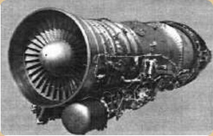
“RB.199”
-The latest version is the 16,400 lbf RB.199-104 with afterburner. It has a three-shaft compressor: 3LP, 3IP and 6HP. The turbine has three stages too: 1HP, 1IP and 1LP. Curiously, the by-pass ratio is 1:1.
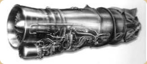
“RB.199-104”
-We continue with the RB.202 project, a small lifting engine of 10,900 lbf. The HS 141 Vtol would use 16 of them. (Plus two RB.220 main engines).
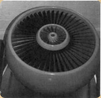
“RB.202”
The RB.203 project known as "Trent", which has nothing to do with the well-known first Trent turboprop that was derived from the Derwent.
-Nor with the Trents that followed, which were the largest engines built by RR for the B-777, A-330, even for the A-380, and as we will see they are derivatives of the RB.211.
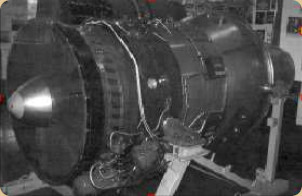
“Photo of the Trent, by John Martin”
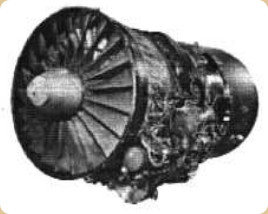
“Second engine to bear the Trent name”
-Continuing with the numerical order of projects we arrive at the RB.207.
-In its day, the existence of a large engine in the range of 50,000/55,000 lbf was known, the RB.207. It was intended for large “Wide-Body” aircraft. It was canceled in favor of the RB.211.
-Initially it was selected for the European Airbus A-300.
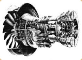
“RB.207”
-The RB.211 have been a family of high-power, three-shaft, high-by-pass, high-pressure-ratio turbofans.
-The expected thrusts were between 37,000 lbf and 95,000 lbf.
-The -22B series gave 42,000 lbf and was installed on the English Tristar. The engine was built in seven, easily interchangeable modules.
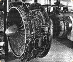
“RB.211-22”
-The "524" have been another series that easily reached 53,000 lbf of thrust.
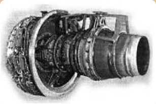
“RB.211-524”
-Now we come to the -535 version of which there are also series, and that has turned out to be a great engine.
-If the first RB.211-22B entered service in 1972, the -535 would do so ten years later and was destined for British registered Boeing-757 aircraft with ETOPS capacity (120 minutes) in the E4 model.
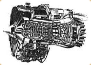
“524, with suppressor”
-The thrust of the RB.211-535 was between 37,000 and 45,000 depending on the variant.
-Actually they are somewhat smaller than the -524 and are more commonly known as the “535”.
-The reduced 524 had project designation RB.235 and is precisely what would be the "535".
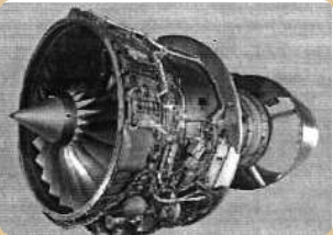
"RB.211-535"
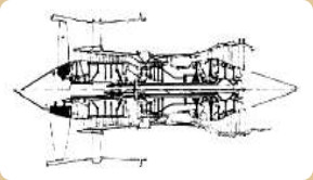
“524 vs 535”
-The RB.220s were turbofan engines giving 27,000 lbf, and were destined for HS 141 VTOL aircraft. (see topic RB.202).
-The RB.225 were bypass turbofans, essentially they were Spey engines with a remodeled Fan to give a greater By-pass ratio, perhaps this led to the Tay.
-The RB.227 project was a lift engine, like the RB.228, -the latter somewhat larger-. It was destined for the BAC P.71 aircraft of the Royal Navy.
-The RB.231 was a small turbofan for the “Super Gnat” (HS 1203) aircraft. We have no more information, for now.
-The RB.235 was already said to be a reduction of the RB.211-524 to become the -535.
-The RB.236 and RB.238 were small turbofans for the HS 1215 and HS 1200 aircraft respectively.
-The RB.277 was once again a lift-engine, with the intention to be mounted on the HS 1192.
-Interestingly, the RB.318 was a small 600 SHP turboprop that was transferred to Alfa Romeo, which manufactured it as AR.318 (see).
-The RB.346 project was another small turbofan, with a possible destination for the above mentioned HS 1200 as well.
-The RB.401 was a small turbofan that ran in 1973 with a thrust in the order of 5,000 lbf. But its continuity was not authorized.
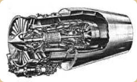
“RB.401”
-The first RB.401 design from 1973 was the RB.401-06. It ran for the first time in 1975. It was a small turbofan, and was developed until it reached the RB.432.
The RB.406 was a variable cycle engine that was destined for the HS 1198 fighter project.
-The RB.409, a small 9,700 lbf turbofan, was planned for the HS 1204 fighter (under study).
-The RB.410 was a development from the French Snecma M45 engine, rated at 14,350 lbf.
-The RB.422 was a Pegasus that was developed to have an afterburner in the forward nozzles (HS 1216 SVTOL) delivering 31,400 lbf dry and 44,600 lbf with afterburner.
-The RB.431 project seems to have been a Pegasus with straight outflow from the engines. It had no nozzles and was used for studying.
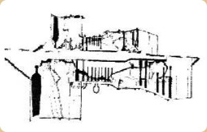
“RB.401 vs RB.432”
-With the RB.432, a turbofan that delivered 16,000/19,000 lbf, Rolls Royce contributed for the development of joint programs such as the RJ500 and the V2500.
-The Pegasus RB.508 gave 26,000 lbf of thrust. It was considered for high temperature operation (Pegasus 18).
-The RB.509 was a propfan with contra-rotating rotors, giving about 13,000 SHP. The RB.529 had the highest bypass ratio with fairing, and was commonly called the “Contrafan”.
-The RB.533, a vectored thrust turbofan with afterburner, was planned for the BAe P.1229 (British Aerospace absorbed Hawker Siddeley, Hispano Suiza and others). The RB.535, turboprop used a Dart gearbox, and had a RTM322 core.
-The RB.543 led to the “Adour” and the RB.550 served to experiment the modular construction of a turboprop based on the RTM 322, of 3,200 SHP.
-For the naval version EFA aircraft, a hybrid engine was experimented with, combining elements of the EJ.200 (of the Eurofighter) with those of the Pegasus. It was the experimental RB.571.
-The RB.578 double configuration engine would be a combination derived from the F406-RR-408 manufactured by Rolls-Royce and could act as VTOL and as a conventional jet giving 25,000 lbf dry and 41,000 lbf with afterburner.
-The RB.580 is a turbofan derived from the Allison T-406 for small business and regional jets. It gives 7,100 lbf of thrust.
-Like the piston Eagles that repeated their name on three families of engines, this has also happened to the Trent: in the Derwent modified for turboprop, the small turbofan of 1967 and the one that appeared recently, in the 1980s/90s, the most powerful engine of Rolls-Royce.
-These last Trent engines have nothing to do with the previous Trent. It was said that the new Trents were actually based on the RB.211-524L.
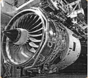
“RR, Trent”
-So far- the 500, 600, 700, 800, 8104, 900, 1000 series have been produced and it goes to the 1500, 1700. A marine version is the MT.30.
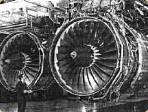
“The RB.211 and the Trent”
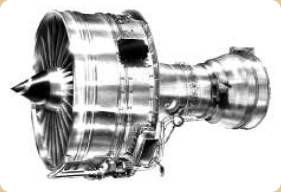
“Trent 500”
-It was intended for the Airbus A340-500 and 600, with ETOPS capability. The diameter of the Fan is 247 cm.
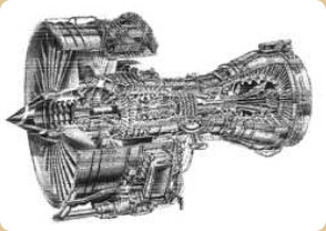
“Trent 500, cutaway”
-It has three shafts, one for the fan and two for the compressors. Thus, a 1LP turbine for the fan, an IP turbine for the 8IP compressor and a HP turbine for the 6HP compressor.
-The Trent-566 version gives 56,000 lbf of thrust and the Trent-553 delivers 53,000 lbf.
-They are installed on the A340-600 and -500 respectively. The latter can reach a distance of more than 8,700 nautical miles.
-The Trent 600 engines are a family intended for the Boeing 747 under development. They are in the range of 60,000 lbf of thrust.
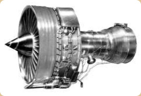
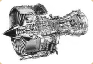
“Trent 700, normal and cutaway”
-They were destined for the Airbus A-330. Trent 700s have been offered in the 67,500 lbf 768 series. The 71,100 lbf 772 and the 772B gave the same thrust.
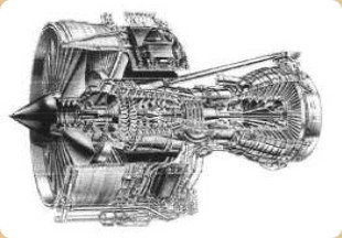
“Trent 800, cutaway”
-The Trent 800 was destined for Boeing 777 aircraft, with almost 500 engines built up to 2004. They had thrusts between 75,000 lbf and 95,000 lbf.
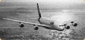
“Airbus A-380”
-The Airbus 380 has its Trent in the 900 series, certified up to 80,000 lbf.
-The Trent 1000, of 53,000/75,000 lbf, entered service in 2008 to power the Boeing-787.
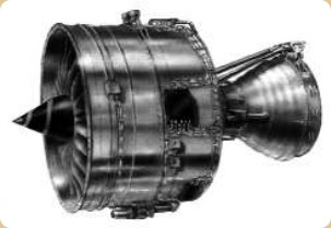
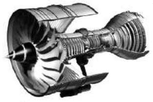
“Trent 1000”
-The Trent 1000 will alternate with the GE GEnx on the Boeing 787. Available from 2008.
-The diameter of its fan increases to 283 cm. and the compressor and turbine stages are: 1LPC, 8IPC, 6HPC, 1HPT, 1IPT and 6LPT.
-The Trent 8104 was assigned to the B-777-200LR and -300ER and the power was huge, surpassing the magic line of 100,000 lbf, they reached 114,000 lbf and were tested at 117,000 lbf. Although later it was relegated.
-The Trent 1500 was made to replace the Trent 500 in the same aircraft models. The gas generator comes from the Trent 1000.
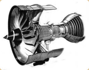
“Trent 1700”
-The Trent 1700 is similar to the 900 and a variant of the 1000. It is destined for the A-350 and 75,000 lbf.
-It was mentioned at the beginning of the Trent that there was a marine version, the MT-30. It was derived from the Trent 800 with a Trent 500 gearbox, and it produced 30 megawatts. It is suitable for the turboelectric ship propulsion. Or to use the direct transmission in propellers or "waterjets".
-As we already know, Rolls-Royce brought together the entire aeronautical motor industry in England.
-R-R received the engine sections (factories, documentation, material, personnel, etc) from De Havilland, Blackburn, Cirrus, Napier, Bristol-Siddeley (and therefore Hawker-Siddeley y Armstrong-Siddeley), etc.
Rolls Royce kept those engines that could be interesting and useful. As a review let's see the ones that were still active.
“BS, Gnome”
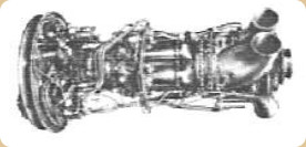
“Napier Gazelle”
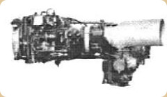
“Blackburn Nimbus”
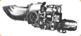
“Blackburn Artouste”
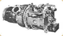
“Blackburn Palouste”
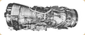
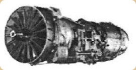
“Bristol/Snecma, Olympus 593”
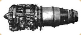
“AS, Viper”
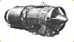
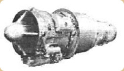
“Bristol, Orpheus”
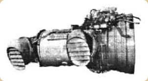
“Bristol, Pegasus”
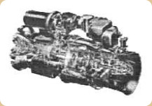
“Bristol Siddeley 360, RS-360”
-Only some of the most important "inherited" engines have been shown. The Olympus was designed by Bristol and later manufactured by RR/Snecma in its 593 variant and it was the engine for the SST Concorde.
-Orpheus' and Viper's histories would fill many pages in this publication. The Armstrong Siddeley ASSa.7 Sapphire was the first axial compressor turbojet to operate in Great Britain. It was derived from the Beryl, which was originally an engine from Metrovick, a company that was also inherited by RR.
-From Rover they had the turboshaft version of the 2S/75 auxiliary engine called "Ryton" that gave 75 SHP.
-The “Solent” was also an auxiliary engine from Plessey, used as an auxiliary power source for starting the Spey engine on the British F4K/M Phantom. It gave 70 shp. (There exists another Solent piston engine: see Plessey.)
-Turboshafts such as the Bristol BS-360 belong to the group of helicopter engines such as GEM, Gnome, etc.
-The Gnome (see Bristol) are the same H-1000, H-1200, H-1400 and H-1400T, (and the P-).
-The RR-1004 is almost identical to the GEM.
-Here the powers are also increasing with the development of engine models. Most of the GEM engines appeared between 1975 and 1987. The GEM 2 only gave a maximum continuous power of 750 SHP, for 5 minutes it gave 830 SHP.
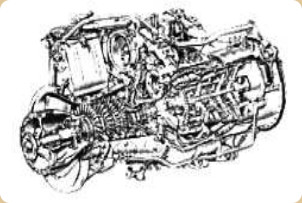
“RR-1004”
-The RR-1004 had its continuous maximum at about 815 shp and a contingency maximum of 952 shp for 25 minutes and a 20 second emergency of 1,035 shp.
-The GEM-41 and -42, as well as the GEM-60 were almost identical, varying in the powers they delivered.
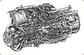
“GEM-60”
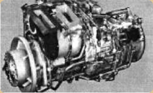
“RR-GEM”
-Other engines have been the result of international cooperation, for its quality Rolls-Royce has been requested to intervene in projects and developments in other countries.
-Cooperation with France has clearly been with Snecma and Turbomeca.
-With Snecma, the main engines have been the Olympus 593 and the M45H.
-In its day, in 1964, the M45H, with 3,500 Kgf of thrust, was an advanced turbofan. (See Snecma). This was the RB.410 project.
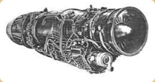
“RRTL - Adour”
In 1966, a joint company with Turbomeca was formed with headquarters in London. The Adour would emerge from this company. This engine was in the 8,000 lbf range and with a growth potential that was demonstrated later. RRTL is short for Rolls Royce / Turbomeca Limited.
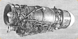
“Adour”
-The 8000 lbf of thruat was given with afterburner, the maximum at takeoff was 5,300 lbf without afterburner.
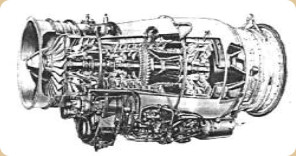
“RRTL-Adour without afterburner, cutaway”
-As we know from previous references, the Adour is a development based on the RB.172 and RT260. The diameter of the air intake was only 22 inches.
-Its most important application is on the SEPECAT “Jaguar”, but it also powered the Fuji F1 and F2, as well as the Hawk and Goshawk.
-It has been manufactured under license in Japan by IHI under the reference TF40-IHI-801A.
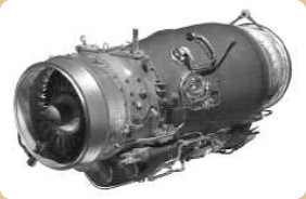
“Current Adour”
-The recent Adour Mk951, gives 6,500 lbf without afterburner, the same as the Mk871 (F405) with 6,000 lbf. The MK106 and Mk811 give 8,430 lbf with afterburner. All of them with 2LP and 5HP compressors and 1HP and 1LP turbines. These are the versions currently in production.
-With Turbomeca they also made the RTM-321 turboshaft with free turbine and two shafts. It was announced in 1979.
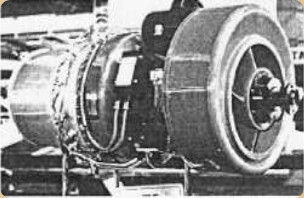
“RTM-321”
-The RTM-321 gave 1,750 SHP and was destined to Westland/Agusta WG34 Sea King helicopters.
-The RTM-322 delivered 2,100 SHP with the possibility of increasing its power to 3,000 SHP. The first ones came out around 1988 with plans to be installed on the EH-101, Westland 30, etc.
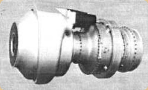
“RTM-322 scale model”
-The first RTM322 had the following performances at sea level:
-Maximum contingency: 2,308 SHP.
-Maximum takeoff: 2,100 SHP.
-Typical Cruise: 1,260 SHP.
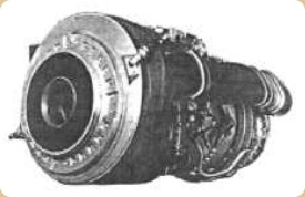
“Real view of the RTM-322”
-The collaboration with MAN, MTU and Fiat of certain engines has already been mentioned, for example the RB.199 for the Tornado aircraft.
-There have been agreements with Russia for joint projects with Lyulka/Saturn.
-Within the IAE joint venture, there was the V2500, a large turbofan that started with 23-25000 lbf of thrust. See IAE. Made in the USA.
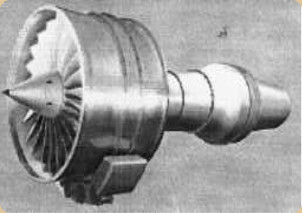
“IAE, V2500”
-The GEM-2 was made by agreement at Piaggio as well.
-With KHD (Klockhner-Humboldt-Deutz) an APU was made jointly for German projects around 1967 (eg the VAK191B). This was the T-112.
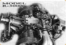
“RR / KHD, T-112”
-Rolls Royce and Turbomeca set up a Division in Brazil, at first with the intention of providing service and maintenance in South America, for the Arriel engines of Ecureuil helicopters and the engines of AMX military aircraft.
-In the USA with "AE" (see), it builds the AE-1107C "Liberty" engines, the AE-2100A, C, D2, D3 and the AE-3007A, H, etc.
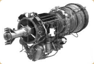
“AE-1107C “Liberty””
-The Liberty is the engine intended for the Bell Boeing V-22 Osprey, a vertical takeoff plane/helicopter but it tilts its two large rotors to move forward as well.
-They are used by the Global Hawk (RPV) and the Embraer-145VE. The AE-3007-A1P engine gives 7,580 lbf and the -H version gives 8,600 lbf. Both with 1LPC, 14HPC, 2HPT and 3LPT.
-The AE-1107C gives 6,150 SHP with a 14HP compressor architecture and 2HP and 2PT turbines.
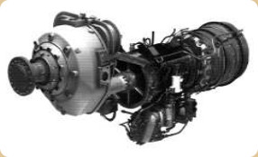
“AE-2100”
-The AE-2100 are of the order of 4,500 shp. Thus R-R currently has in production the -D2 of 4,637 shp, the same for the -D3 and an AE-2100J model of 4591 shp. The AE-2100-D3 engines power the Hercules C-130J.
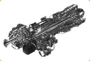
“AE-2100, cutaway”
-The AE-3007s are turbofans of the 8,000 lbf range, being used in corporate, regional and military aircraft. More than 2,200 engines have already been manufactured.
-They are used by the Global Hawk (RPV) and the Embraer-145VE. The AE-3007-A1P engine gives 7,580 lbf. and the -H delivers 8,600 lbf. Both with 1LPC, 14HPC, 2HPT and 3LPT.
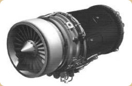
“AE-3007”
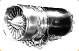
“Another AE-3007”
-Regarding North American Allison, not only did R-R start collaborating but it ended up acquiring the company. Today Detroit Diesel Allison engines are Rolls-Royce.
-More than 29,000 engines of the 250 model have been manufactured. The 650 SHP Models C30R/3 and the 420 SHP T63-A-720 are currently in production as turboshafts. They are used in many helicopters and other devices.
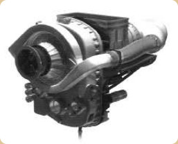
“Allison 250-C30”
-While the C30R/3 uses 1CFHP and 2HPT, 2PT, the T63 has 6HP+1CFHP and 2HPT, 2PT.
-The B17F turboprop version is offered for Extra, Fuji, Grob, Schweizer and Enaer aircraft.
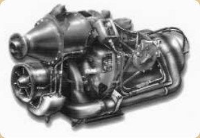
“250-B17F model”
-The T-800 and CTS800 turboshafts for helicopters such as the Super Lynx and A129 Mangusta have also entered the R-R orbit.
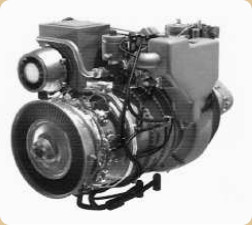
“T-800 / CTS800”
-The CTS800-4N gives 1,362 SHP and the T-800/LHT-801 delivers 1,563 SHP.
-Thee were the original engines on the Hercules, Orion, Hawkeye and Greyhound aircraft. The T-56, now is Rolls-Royce.
-The T56-A series III (4,591 SHP) and series IV (5,250 SHP) models with more than 18,000 engines built, and some 300 million flight hours, are considered very successful engines and still havw the possibility of being operational by the year 2020 .
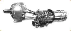
“T-56”
-With the American Williams, the FJ-44, FJ-33 and FJ-22 models were projected and developed, becoming known as RR/Williams. They were installed on business jets such as Citation Jet, Premier, etc.
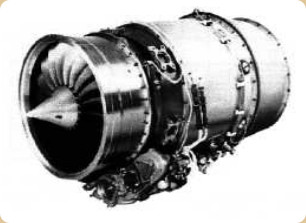
“RR / Williams FJ-44”
-Rolls-Royce forms a group with Snecma, ITP and MTU for the engine of the future European military transport A400M for the new company EPI or "EuroProp International GmBH".
-The engine for said plane is the one produced under the reference TP400-D6, delivering more than 11,000 SHP, or rather, it starts off from this power for further development.
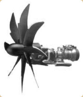
“Europrop Int’l, TP-400D6”
-In Germany Rolls-Royce founded "Rolls-Royce Deutschland Ltd & Co KG", whose best-known projects have been the BR engines in collaboration with BMW.
“BR-700TP”
-MTU, Fiat, ITP, TA and Snecma also participated in the BR-700TP turboprop project. Perhaps it was the one that gave way to the TP-400. At the end of the previous century it was in evolution but the news has faded.
-The BR-710 is a two-shaft, high-by-pass turbofan.
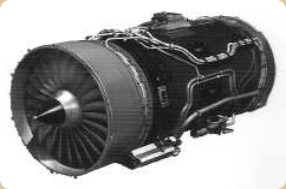
“BR-710”
-The BR-710A1-24, currently in production gives 15,000 lbf, and is used on the Gulfstream C-37A, Bombardier Global Express Astor and the BAe Nimrod MRA4.
-The BR-710 was certified in 1996 for long-haul business and regional aircraft such as the Global 500 and Gulfstream V.
-The BR-715 is similar and entered production in 1997. It is based on the above mentioned BR-710.
-It gives more power since it reaches 20,000 lbf. BR, are the initials of BMW / Rolls-Royce collaboration.
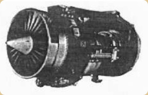
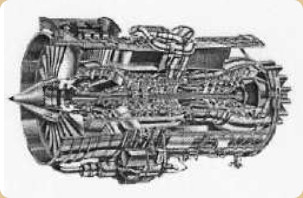
“BR-715 photo and cutaway”
-In Japan RR / JAEL was created, that is, the Rolls-Royce / Japanese Aero Engines Ltd. This consortium was especially created to manufacture the RJ.500.
-The Japanese part was a group formed by IHI (Ishikawajima), KHI (Kawasaki) y MHI (Mitsubishi).
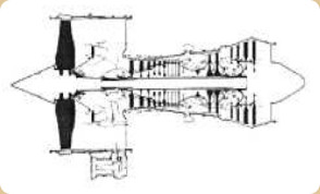
“RJ.500”
-The RJ.500 was a turbofan that first ran in Derby (an R-R factory in England), in 1982. It delivers 20,000/25,000 lbf. The second engine was made in Japan in the same year.
-With the MTR consortium, the MTR-390 is made for the Eurocopter Tiger attack helicopter. The consortium is made up of MTU, Turbomeca and R-R.
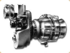
“MTR-390”
-An almost unknown Rolls Royce project was the XG-40 engine. It was a research project that began in 1983 aimed at advanced combat aircraft.
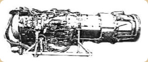
“XG-40”
-It was tested in 1986 and considered a two-shaft turbofan with an augmentation system.
-The By-pass air from the turbofan does not circulate in parallel around the engine but is reintroduced for a second combustion.

“Reheated by-pass engine”
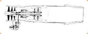
“XG-40 schematic drawing”
-A second prototype provided enough technology that Rolls-Royce would introduce in the Eurojet EJ-200. Above we see a schematic cross-section drawing of the XG-40 prototype.
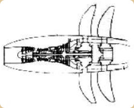
“Possibly the RB.549”
-Another engine not mentioned in the list of RBs- was the RB.545 that was eventually oriented for the HOTOL program. It seems to be a turbo-rocket engine from the year 1992. it used air, LOX and LH2, and It delivered 82,660 lbf of thrust.
-To have an idea, the projects are from many years ago. The one shown below belongs to a Rolls brochure from the 1960's.
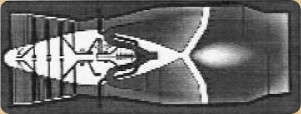
“R-R Turbo-rocket engine”
-This project and another similar one became known as HOTOL, a space shuttle vehicle with “HORizontal Take Off and Landing”.
-The RB.545 has been secret until there was a trickle of information after the HOTOL program was abandoned.
“RB.545 concept”
-This engine is similar to the Sabre engine from Reaction Engines Ltd. (see) due to the fact that it takes atmospheric air at a low level and changing to liquid oxygen in the stratosphere. See also "Scimitar" that had a similar principle.
“HOTOL Shuttle”
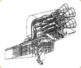
“Air intakes ands 4 x RB.545”
-Below we will review the rocket type engines received from Bristol, AS, etc.
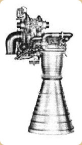
“RZ.2”
-This rocket motor ran on liquid oxygen and kerosene, giving 150,000 lbf of thrust. It was used in the English Blue Streaks that were tested at Woomera.
-The development of this engine was done while R-R was supported by the Rocketdyne Division.
“Launching a Blue Streak”
-A double installation of RZ.2 engines can be seen below (later it became the RZ.12). Note that the exhaust pipes of the turbopumps are adjustable at the end (vernier), used for stabilizing and guidance.
“Double installation of the RZ.2”
-The evolution of the RZ was progressing until the RZ.20 that we will show. It was already running on LOX and Liquid Hydrogen.
-For the ELDO program, under contract, the RZ.20s were made for the upper stages B and C of the Eldo that the French proposed in 1964.
“RZ.20”
-Cluster engines such as the Gamma, type 4, was used on the Black Knight research vehicle with 25,000 lbf of thrust at sea level and using HTP and kerosene.
-Previously Gamma Type 2 was mounted together on the first stage of the Black Arrow launcher.
“Gamma 8”
-The Type 8 Gamma, was a set of 8 engines giving 50,000 lbf of thrust in total. They were used for launching British satellites in 1969.
-Another rocket engine was the Stentor, a twin-chamber, take-off and cruise, used in Hawker-Siddeley's airborne flying bomb, the Blue Steel.
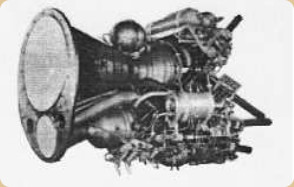
“Stentor”
-It used HTP and kerosene. Engine collector Mr. Castellseguer (from BCN) owns a perfectly maintained unit.
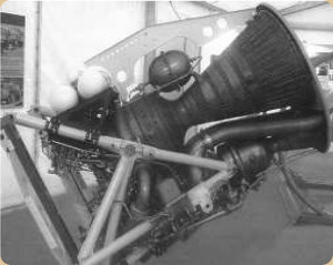
“Stentor exposed in Barcelona”
-The PR.37/2 engine (see Bristol and Armstrong Siddeley) is considered a Booster that was mounted on the Australian Jindivik missile for high altitude (it had a Viper SL as a sustaining engine). It gave 170 lbf of thrust.
“Bristol Siddeley BS.605”
-The RR.605, a retractable rocket motor for take-off assistance, gave 8,000 lbf of thrust, and was used by English Buccaneer planes, among others.
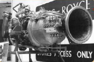
“BS.605, Photo by G. Brosset”
-R-R also took over the Odin and Thor ramjets from Bristol.
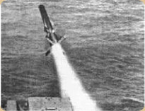
“Launching a Sea-Dart”
-The Sea-Dart surface-to-air missile has an Odin ramjet (see also Bristol), with a secret thrust.
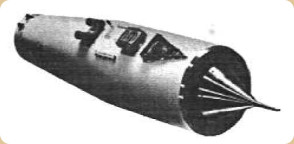
“Thor ramjet”
-The Thor, with 6,900 lbf of thrust at Mach 2.2, was mounted on the Bristol-Ferranti Bloodhound, a surface-to-air missile used in various countries such as Australia, Switzerland, Sweden and Great Britain.
-Before finishing the Rolls-Royce chapter, we are going to see how Rolls-Royce aviation engines are used industrially or maritime, another important facet of the brand.
-The most important engines have been modified for their adaptation, as we will see below.
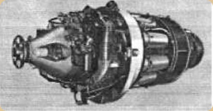
“Marine Proteus”
-The 4,500 BHP (BHP = Brake Horse Power), are obtained with the Proteus, a lighter and shorter engine than piston engines. Ideal for patrol boats and torpedo boats, "Hovercraft" and "Hydrofoils".
-With 5,340 BHP up to 6,000 BHP, the marine Tyne was developed from the aero engine and has its application in being a cruise engine in the most advanced warships of today.
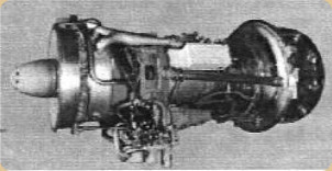
“Marine Tyne”
-The industrial Olympus with mechanical transmission for 32,300 BHP, can generate up to 30 MW.
-Being a fixed and stable installation, it can run on liquid or gaseous fuels, or with dual operations at convenience.
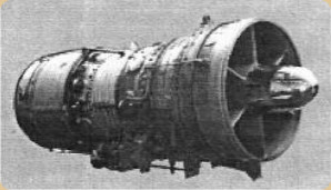
“Industrial and Marine Olympus”
-The marine version runs with powers from 28,000 to 29,600 BHP. They are used on warships for high speed operations.
-It was used in modules or groups on the Invincible-class aircraft-carriers, for example.
-The industrial Avon engine has mechanical transmission and powers from 16,000 to 20,000 BHP.
-It can drive an electricity generator of up to 18 MW.
-Ideal for remote operation control, it can be used in "pipeline" pumping stations or power stations, controlled by terrestrial or microwave radio systems.
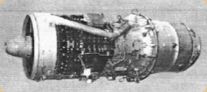
“Industrial Avon”
-It can also run on gaseous, liquid or combined fuels. Even with those transported through the pipelines.
-The industrial Spey version delivers 16,400 BHP. It can drive a generator of up to 14 MW.
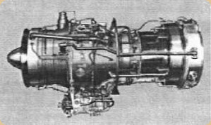
“Industrial and Marine Spey”
-It has low cost and consumption (sfc.), without the complications of regenerative plants.
-Inspections of hot areas or "Hot Section Inspection" (HSI) can be carried out "in situ" ensuring maximum engine life.
-The marine version of the engine gives 17,100 SHP. It was the first engine used in modules of the SM series designed to give maximum efficiency for high speeds and sustainable cruising of warships.
-The industrial RB.211 gives 29,600 BHP for generators to produce 24 MW. They are of modular construction and have disposition of parts working according to the Surveillance and "On Condition" criteria, This saves time and maintenance costs.
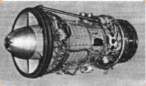
“Industrial and marine RB.211”
-The RB.211 marine engine, with similar power to the industrial one, is used in prospections in the North Sea.
-It is also particularly suitable for use on ships operated with LNG, or Liquefied Natural Gas.
-So far the text that appeared in the 2003 Edition of this publication. We now add an Appendix 1, of the revisions of the year 2006.
Appendix 1:
-Received some schematic drawings of various motors of the brand that we introduce for the moment until the receipt of the permit (PeT).
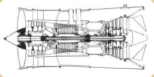
“RB.183-03 Tay”
-In the Tay-03 project, Volvo also participates with less than 5%. This engine is derived from the Spey (RB.183-Mk-555).
-It is mounted on the Fokker-100, Gulfstream V and it was also used for repowering some of the old B-727.
-Below we show the 535E4 version of the RB.211 for B-757 and other aircraft.
-Even some of them repowered Russian aircraft like the Tu-224.
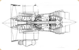
“RB211-535”
-Although they seem from a previous generation, the RB.211-524G/H are derivatives of the 524D and are using the core of the Trent 700 (B747-400 and B767).
-The 524G/H give between 258 to 280 kN respectively. As a curiosity a 524B ran for 27,523 Hrs. before taking it down for general review. And several G/H passed 20,000 hrs.
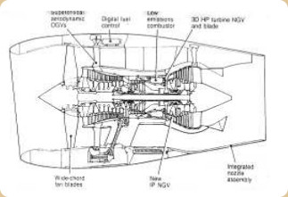
“RR, RB211-524G/H”
-The Trent 500 engines were built jointly with Fiat Avio, ITP, Fokker Elmo, Lucas (pumps), Aircelle (nacelas), Hispano-Suiza (gearboxes), Hamilton-Standard (FADEC) and IHI, Marubeni (Japan).
-They were mounted on some Airbus 500/600 until 1999.
-Trent 553 and 556 versions give 53,000 and 56,000 lbf respectively.
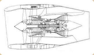
“Trent 700”
-Below we show a half-cross-section of the Trent 800. In this project IHI, Lucas, ITP, KHI, Hispano Suiza and Denel participate with R-R, adding 23.5%
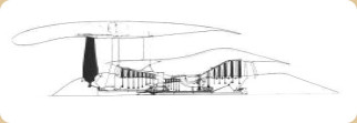
“Half-cross-section of the Trent 800”
-The Pegasus engines were inherited by Rolls-Royce from Bristol.
-They are the engines that were used on the Harrier S/VTOL and the American AV-8B.
-That is why these engines are also made in the US by Pratt & Whitney (25%) under the F402-RR-408 specification (the Pegasus 11-61). They gave 97 kN of thrust.
-They are double flow military engines having a double body with adjustable nozzles.
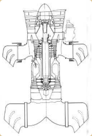
“Pegasus 11”
-We also have the Spey, in a longitudinal cross-section. There are many variants with their thrusts oscillating between 44 and 90 kN.
-For example the Mk511 with 51 kN on the Gulfstream II/III.
-The Mk512 on the BAe Trident and NAe 1-11 gives 53 to 56 kN.
-The Mk555 has been mounted on the Fokker-28. The Mk202s that gave 91.2kN with afterburner were mounted on the RAF Phantom F-4s. The Mk250 on the Nimrod with 53 kN or the Mk807 of only 49 kN on the Aerotalia/Embraer AM-X.
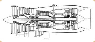
“RR Spey”
-The Vipers were interesting as they were born as expendable engines for missiles. They turned out to be of such extraordinary quality that they were adapted and used in military and civil aviation, also with a life between OH, or TBO of 5,000 Hrs., which was superior to anything known at the time of its release. This engine gave 18 to 25kN of thrust.
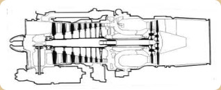
“Viper”
-Now we mention the Adour, a turbojet built by a consortium RR/Turbomeca.
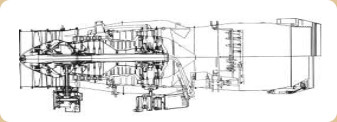
“RR/Turbomeca Adour”
-Actually, it is derived from the RB153/172. With a thrust of 37 kN it is used on British and French Jaguars, and also on the Japanese T-2 and F-1.
Rolls-Royce Deutschland Ltd & Co KG began with the development of the BR710 and BR715. The latter delivered 85kN and was used on the B-717.
-The BR710s are mounted on the Gulfstream V, Canadair Bombardier Global Express and on the TU-334 of Russian regional transport. They gave 65 kN of thrust.
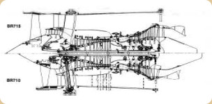
“BR715 vs BR710 comparison”
-Other R-R engines in collaboration with the Allison Engines Company (today fully absorbed by R-R) were the AE3007 A and C of about 32kN and which was to be immediately developed into the AE3008.
-The turboprop version of the core of this engine would be the T-406 of 4850 kW for the V-22 Osprey. This was the AE2100 engine.
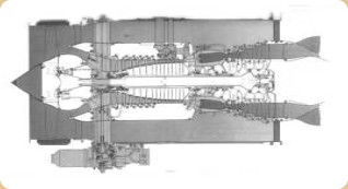
“AE3007”
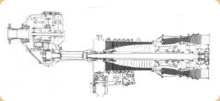
“AE2100”
-In addition to the Ospreys, the AE2100 is also installed on Saab-2000 Commuters, IPTN N-250 and Lockheed C130-J.
-Below we will treat the Olympus motor of the Concorde, model 593/610. The gas generator was made by R-R and the nozzle and afterburner by Snecma. It gave 170 kN of thrust.

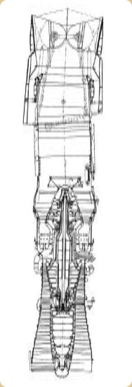
“Olympus 593/610”
-And below some Rolls-Royce advertisements that appeared in the specialized press, referring to their engines and their progress.
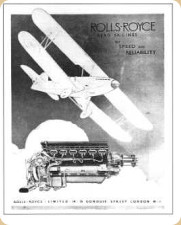
“Rolls-Royce ad from 1932”
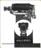
"Rolls-Royce ad from 1937"
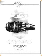
"Rolls-Royce Dart ad from 1950"
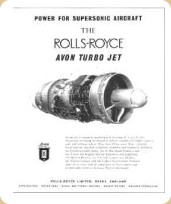
"Rolls-Royce Avon ad from 1958"
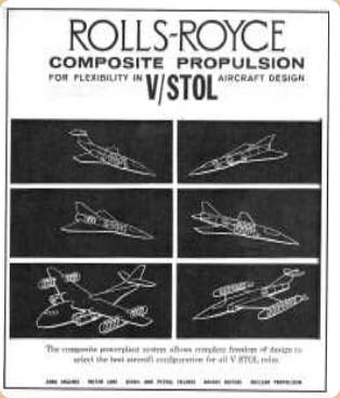
“The interesting Rolls-Royce advertisement for V/STOL aircraft”
-This last ad offers us a range of compound propulsions in which vertical engines such as the RB.162 are used.
-In a second Appendix 2 of the same year 2008, we add received material and other images taken from various museums and collections:
-The Contrafan was a very high by-pass ratio engine. Towards the end of the 1980's it was considered the next generation engine for commercial long-haul aircraft.
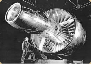
“Contrafan engine”
-As its name indicates, it is an engine with Fan rotors turning in opposite directions. This is the case of the Rolls-Royce RB-529.
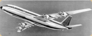
“Proposed aircraft with Contrafan engines”
-We continue with the collaboration of Rolls-Royce with Pratt & Whitney, MTU, Fiat Aviazione and JAEC constructing the V-2500.

"IAE collaborator logos"
"Logos" of the collaborators within IAE (see) for the creation of the V-2500 engine. Below, the IAE logo and the V-2500 engine.

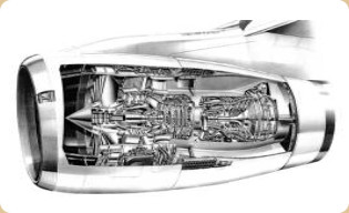
“IAE logo and the V-2500”
-Below we introduce a new localized photograph of the Rolls-Royce XG-40 engine in final tests.
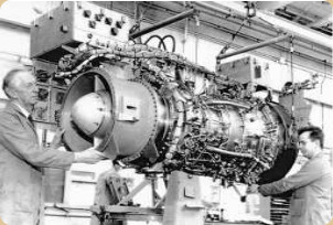
“Rolls-Royce XG-40”
-The evolution of the Pegasus engine, reaches the 11 model in which a new combustion is created at the outlets to give additional thrust.
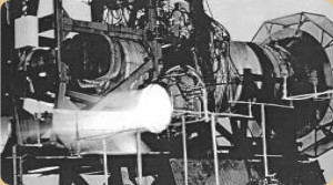
“Pegasus 11 on bench”
-It's like adding an afterburner to the normal engine. We have the photos on the bench and tests with the engine already installed in the Harrier plane and on a test bench.
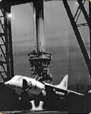
"Pegasus 11 tests on the Harrier” (PiP)
-And now a rare view of a dual Olympus 593 engine mount on the LH or Port side of the Anglo-French supersonic Concorde transport aircraft.
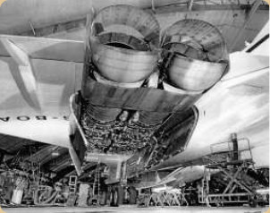
“Two Olympus engines on the Concorde”
-The Olympus on the Concorde used reverse -which we see clearly- and also afterburner, which is extraordinary in a civil aircraft. At takeoff with the exhaust jet flame behind it. the noise that the plane made, did not leave us indifferent.
Note from the author.- Being inside Heathrow Terminal 4 during the takeoff of a Concorde, it was like being inside a sounding board and the vibrations were felt like a not very soft earthquake.
“Comparison of the Condor with an F engine”
-We take the opportunity to show the evolution of R-R engines.
-The area of a Condor and an "F", both giving substantially the same power around the year 1929: 525 HP.
-And also to insert the photo of the beautiful Kestrel from the MAE reserve store.
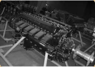
“RR, Kestrel”
-R-R engines are also present in turbine versions, such as the RB-162, at the MAE reserve.
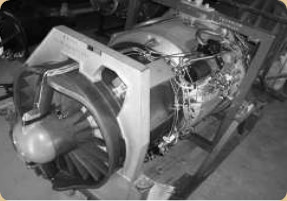
“RB-162 on horizontal stand”
-The RB-162 works in a vertical position, installed inside the fuselages of VTOL aircraft.
-The construction is light because it uses a large amount of composites.
-We discovered another picture of a turboprop of this brand, the Dart, this time a whole one, because there is another beautiful cutaway picture.
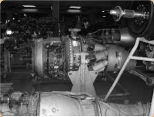
“Rolls-Royce, Dart”
-The Darts were the turboprops that powered the Vickers Viscount and in fact, they became known throughout the world, in civil aviation.
-They also had a great career with the Fokker F-27.
-A Dart that needs to be restored is a part of the private collection "Enginys Mecanics" in Mataró, province of Barcelona.
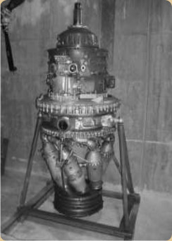
“R-R, Dart upright”
-The inclined combustion chambers of this engine have always stood out.
-In this same collection we can also admire a colossal Griffon, belonging to a four-engine "Shackleton" patrol aircraft.
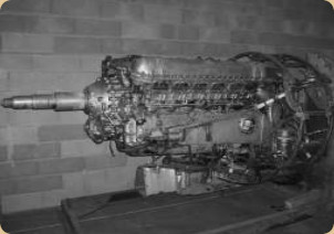
“RR, Griffon”
-For some more details, see the main text. We can see the coaxial and contra-rotating shafts for the double propellers.
-This engine is made according to the QECA (Quick Engine Change Assembly) plan for easy and quick disassembly or assembly on board.
From Appendix 6: The Rolls-Royce Heritage Trust is a kind of museum where all possible history of the company and all the companies that have joined it over the years are preserved. It has its own publications.
“R-R Heritage Letterhead”
-In a quick walk through the Museum rooms we see a few key drivers of UK history.
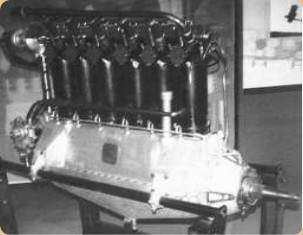
“The R-R Hawk”
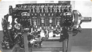
“Merlin, cutaway”
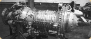
“Clyde turboprop”
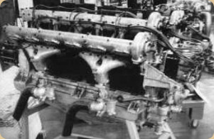
“Sunbeam Cossack”
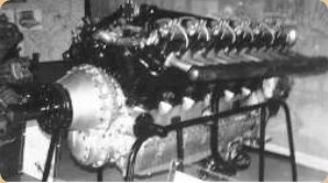
“R-R Condor”
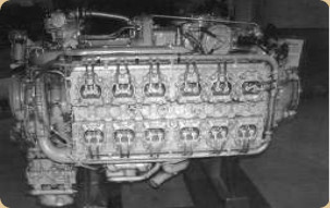
“Napier Sabre”
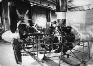
“The hard to locate 1st Trent”
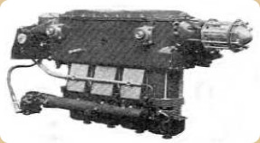
“The Metrovick Beryl”
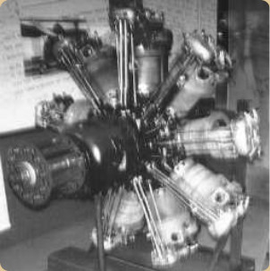
“Bristol Jupiter VIII”
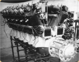
“A Fiat A-14 in the collection”
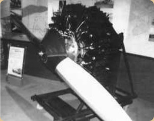
“Armstrong Siddeley Jaguar”
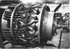
“And a Bristol Centaurus, among many other engines”
Around 1923, a barrel-type engine was made by Rolls-Royce. Although it seems that it was only experimental as a test required by the British aeronautical authorities.
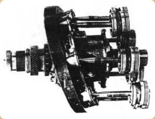
“Part of the Rolls-Royce barrel- or revolver-type engine”
-Photo by Rolls-Royce Ltd. It seems that from 1925 the tests on this type of machine were transferred to Napier. We count 7 pistons.
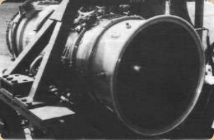
“Rolls-Royce RB-401 for business jets (1980)”
-In the main text no Merlin 62 is shown, like the one we located at the Museum of San Diego, California in the United States.
-Photographed and sent courtesy of MMC and KM.
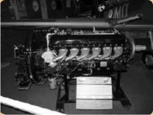
“Merlin 62”
-This engine was specifically donated to the Museum in 1983.
-This engine is from the year 1944, displacing 1,650 cu. in. (V-1650 in the USA) with four valves and two spark plugs per cylinder.
-The main difference with other Merlins is that while the previous ones had a single-stage, single-speed supercharger to obtain 1,030 HP at 16,250 feet, those of the 60 series and specifically the -62 in the photo could deliver 1,860 HP at 10,500 feet and 1,350 HP at 29,000 feet.
-It had a double-stage supercharger with two speeds, it delivered the optimum combat power at 12,500 feet, giving 1,565 HP at 3,000 rpm, with reduction gear of course.
-It also had an intercooler that we see in the upper rear part of the engine.
-About 168,000 Merlin engines were made in total.
-At the Museum of the Italian Regia Aeronáutica we can find the R-R Merlin 500/20. They were mounted on Fiat G59 aircraft.
-At the rear of the engine we see an imposing "backpack" that includes the supercharger and the double carburetor.
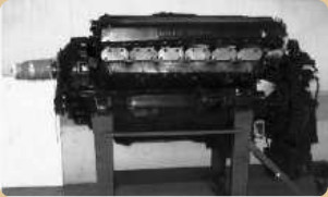
“Rolls-Royce Merlin 500/20”
-Here is a better view of this rear equipment.
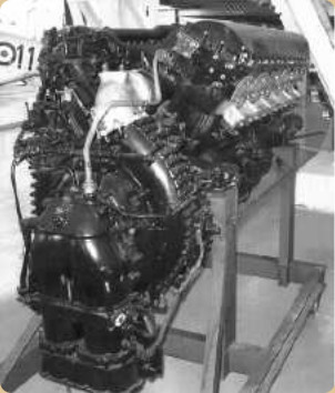
“Rear view of the Merlin 500/20”
-As we know from the main text, during WWII Rolls Royce engines were made in the USA by Packard to equip Mustang aircraft, becoming known as Merlin-Packard V-1650.
-Especially for the P51D Mustang that proliferated at the European front. For this reason it is easy to find these engines in various museums on this continent. In the aid programs they also went to South American countries but for the most part they have not been preserved.
-The one showed below was found in Zurich, Switzerland. A V-1850-7 version with dual two-speed compressor and intercooler.
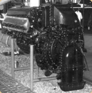
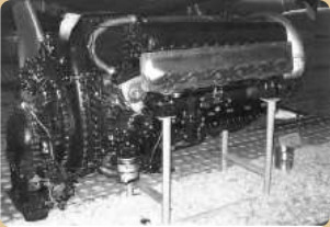
“Two views of this beautiful engine”
-This engine fits perfectly into the nice lines of the Mustang. Compact in shape, as we can see from the semicircular feeder that was at the front of the engine, over the gearbox.
-Just below and driven by an extension of the crankshaft there is the vacuum pump and the "governor" for the propeller.
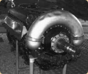
“Feeder on the Packard-Merlin”
-Walking through the halls of the Lucerne Transport Museum, we suddenly stumbled upon a Rolls-Royce rocket engine, the RZ-2, well supported on a metal tube frame.
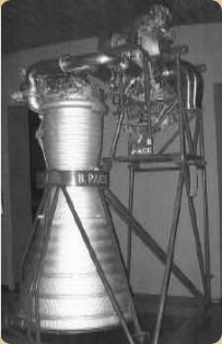
“RZ-2 with its turbopumps and controls”
-The main text mentions an Avon-derived RB.29 engine.
-We have located a photograph at an exhibition in which an Avon is tested on test bench number 7 in Hucknall in the year 1960.
“R-R.29 with Aft Fan” (PiP)
-The main characteristic was that an aft-fan had been attached, near the turbines themselves.
-These experiences would accumulate later for the RB.211.
-However, this engine arose when the brand was pushed by GE engines, the CJ-804-23's (see) that were already mounted on the French Caravelle III, aircraft of notable success at the beginning of the jet transport era.
-Sud Aviation, the constructor of the Caravelle, tried to enter the American market with this combination. Which it did not achieve with GE but with the Pratt & Whitney JT8D-7.
-For the Airbus 350 XWB, Rolls Royce is developing an engine adapted to that aircraft, the Trent XWB. These engines from the Trent family are large turbofans with thrusts that reach 100,000 lbf that some models exceed. See main text -Trent 8104 model-.
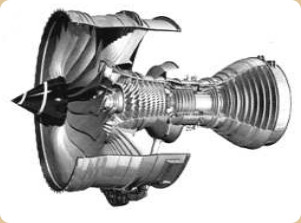
“Trent XWB”
-The thrust of these XWB engines is between 74,000 and 92,000 lbf and the diameter of the fan is 118 inches (about 3 meters).
-In fact, it combines the accumulated experiences of all the Trents and especially the 900 and 1000.
-The Trent is a triple shaft engine and the XWB is the sixth generation of this model.
-The Airbus 350 XWB is a wide-body aircraft (Xtra Wide Body) designed to compete with the Boeing 777 and 787.
-Going back to the early 1930's we show the Rolls-Royce H model. There is no illustration of it in the main text. This one is recently obtained.
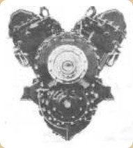
“Rolls Royce H.10, front view”
-The H engine is more powerful than F but they are similar to each other. Precisely the supercharger of the H could be fully used at sea level.
-It had two reduction ratios for the propeller depending on whether it was the H-XII or the H-XIV.
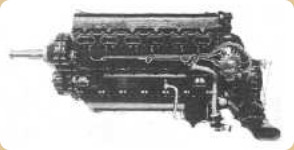
“The Rolls-Royce H.10”
-And the “R” engine was installed on the Supermarine S.6 that won the Schneider Trophy for England. It is a photograph from the year 1931.
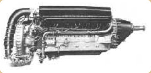
“The R-R model R, “father” of the Merlin”
-At the Lancaster museum, in Canada, there is an R-R (Packard) engine of those built in the USA, with "dash number" -224. It has singular exhaust pipes and no intercooler. It is mentioned in the main text.
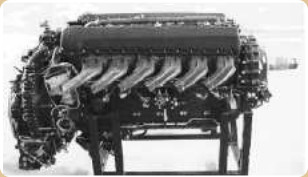
“Packard-RR V-1650-224”
-We have a cross-section drawing of the AJ.65 that would give rise to the Avon.
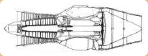
“Rolls-Royce AJ.65”
-Before this 6th appendix, the new series of engines such as the RR300 (old Allison 250) began to be mentioned with little power, 240 to 300 HP.
-Now we have other engines from the same family: The RR500 turboshaft and turboprop. The former is known as the RR500TS and the latter as the RR500TP. The power of both is around 500 SHP.
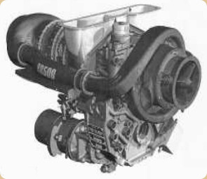
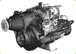
“Both mentioned R-R engines”
-In the helicopter-turboshaft family, and according to the LHTEC program (see), Rolls Royce together with today's Honeywell (former Allied Signal, former Garrett, former AiResearch) currently makes the CTS-800-4N engine, being installed on several appliances and preferably on the Agusta/Westland Super Lynx.
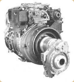
“CTS800-4N”
-The CTS800-4N is from the T800 and CT800 family and the power is between 1,360 and 1,700 SHP.

“T800 Program Logo”
-Now, from the RB.549 project, or derivative, we bring a better view of this aft fan cutaway.
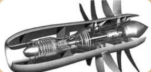
“Rolls-Royce Aft fan cutaway”
-Of the engines that came with Blackburn, the Nimbus was used as an auxiliary group on the RAF Victor bomber aircraft. Now we have located some pictures complete with the large front generator and some extensions for the compressor's air intakes.
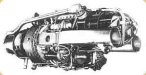
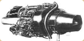
“The Nimbus based on Turbomeca”
-We have received a strange version of the Spey engine adapted to be used on the Boeing/DHC Buffalo.
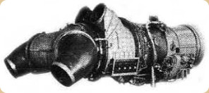
“Spey adapted for the Buffalo plane”
-The exhaust and the Bypass outlet is divided below and above the wing. It is a STOL aircraft with a blown wing, as we can see.
-This plane has had piston engines, turboprops and finally tested the one mentioned here.
-In 1981, the photograph of the Rolls-Royce engine made jointly with the JAE (Japan Aero Engines) RJ.500 was published. See main text.
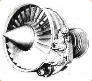
“RR-JAE RJ.500”
-Later, there have been several versions due to its logical development. We can show that in an example of the RJ.500-35-3 and -01 engines.
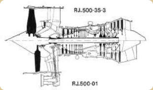
“Evolution of the RJ.500”
-And now a curiosity regarding the typical sound made by the R-R Darts when taxiing and idling, a characteristic “whine” sound.
-This characteristic sound was double in the case of the Fokker F.27 and quadruple with the Viscount.
-The author remembers this sound together with the rocking of the long engine nacelles, randomly some engines compared to others, due to the uneven floor of the Barcelona airport parking runway in the 1950's. It is an unforgettable image.
-In the 1980's and due to environmental noise reduction regulations, this "whine" (bee buzzing too) was attenuated by further separating the propellers from the engine air intakes.
"Modification in the coupling of the propeller" (PeT)
-Regarding the Dart turboprop, a successor came out, the “New Dart” or RB.550. It had an initial power of 3,200 SHP and was capable of reaching 5,000 HP in successive stages.
-It was based on an enlargement of the RTM.322 that R-R makes together with Turbomeca.
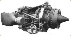
“Rolls-Royce New Dart”
-The main text is missing the Trent 900 and the GEM 42, shown below.
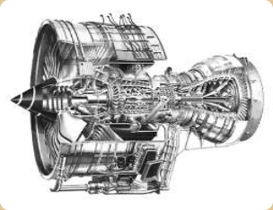
“Trent 900”
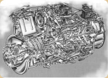
“GEM 42”
-Together with Germany (MTU), Italy (Avio), England (R-R) and Spain (ITP) they manufacture the EJ-200 of the Eurofighter. In fact, the main shareholder of ITP is Rolls-Royce.
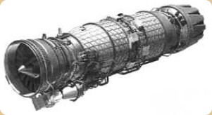
“EJ-200”
-The F-136 is made jointly with the American GE for the F-35 planes that both nations will have.
-It has a rear nozzle that can be directed towards the ground. A forward horizontal fan for lift and stabilizer jets.
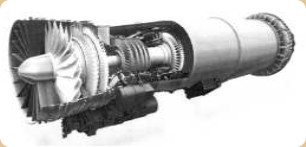
“Turbofan F-136”
-And in 2007, R-R presents the RR300, the first of a new family, based on the 250 for helicopters and airplanes. It delivers 300 HP.
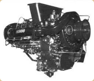
“new RR300”
-The evolution of the Avon turbojet is mentioned in the main text but some engines of which we did not have images we show below.
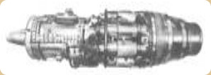
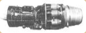
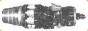
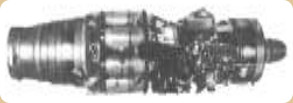
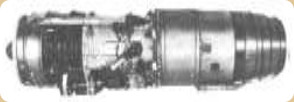
“Five Avon Engines”
-From top to bottom: 1st RA.2; 2nd the RA.3; 3rd the RA.7; 4th the RA.21 and 5th the RA.28.
-Continental piston engines, represented in Europe from the 1960s, were built at the Crewe factory.
-We have located a 260 HP IO-470D that at first was not in the expected production line, but as we can see, it has the RR symbols on the rocker covers.
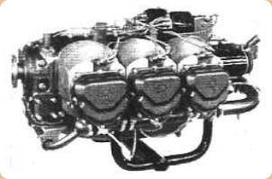
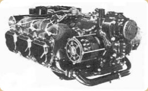
“GIO-470-A”
-Yes, there were two classics made in England, the 0-200, the IO-346 and the IO-360, but the latter was the one that really went well forward due to its installation on the Cessna Reims Rocket and Skymaster.
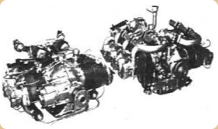
“The IO-346 and IO-360”
-The size of these photos bear no relation to the two above.
-As stated in the main text, the twin-mounted RZ.2 rocket motors on the Blue-Streak became known as RZ.12.
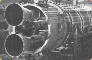
“Installation RZ.12 on Blue-Streak”
-Apart from the Olympus (of the Invincible) and some others of its size, the aviation engines applied to the navy went to relatively light ships such as the R-R Bristol Siddeley 1051 Gnome.
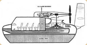
“Air Cushion Vehicle”
-The ACV or “Air Cushion Vehicle” have also been known as Hovercraft.
-The Bristol Siddeley engines made together with German KHD (like the T-312) and later by R-R/KHD, as discussed in the main text, were APUs, like the T-112.
-We take this opportunity to clarify that the "AE" engines refer to "Allison Engines", acquired by Rolls-Royce.
-The Allison TF41-A-1 engine made by RR/Allison for the Corsair 2, like the one in the photo, had no image in the main text. We show one below.
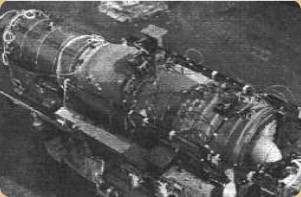
“RR-Allison TF41-A-1”
-Now we deal with the issue of the "fourth" engine of the Trident airliner. This fourth engine was a takeoff aid and could be a Viper or a Rolls-Royce RB.162 for vertical takeoff in a horizontal position, as was the case with the Trident 3B, at that time in the BEA company.
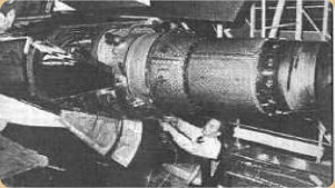
“RB.162 installation on a Trident”
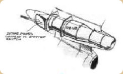
“Flight Magazine Sketch” (PiP)
From Appendix 9: This important brand has the complex rocket motors such as:
-545
-”Sabre” (de Reaction Engines Ltd.”, see)
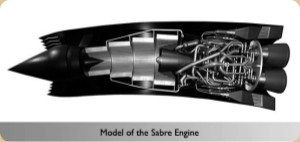
“Sabre”
-It seems that this last engine is in the orbit of R-R.
-The Author of this A-Z edition, in his investigative zeal, has had in his hands a project of which he is insure if it belongs to Rolls-Royce itself, or if it is a proposal from someone outside.
-It refers to a test of a 12-cylinder Merlin in V but with a rotary valve device in the cylinder head instead of the classic “mushroom” type valves.
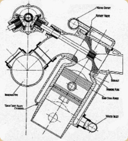
“Distribution and valve diagram”
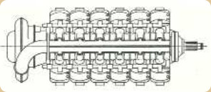
“Top View of Engine Assembly”
-We found new photos of the “Exe” engine, alias “Boreas”, from the last era of piston engines, with unusual formulas such as large engines with X or H cylinders, etc.
-In the first image, simple type deflectors can be distinguished.
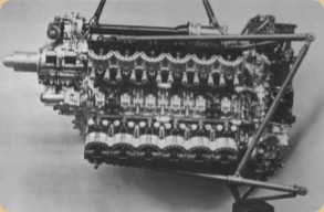
“Normal engine version for the Battle aircraft”
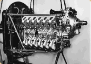
“Exe version with special deflectors”
-These last deflectors are to induce forced air around the cylinders, totally enveloping them.
They give the engine a curious look. It has superimposed reduction gears.
-Another engine is the Pennine, also in X but with a sliding sleeve system to the point that the cylinders are very similar to the Bristol Hercules.
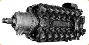
“The Valveless Pennine”
-It had planetary reduction gear. At the front it had a fan to force cooling.
In Lonköping, at the Malmen Museum, there is an R-R Griffon 66, with a propeller (with mutilated blades), which we bring to this publication precisely because of the formidable hub of this propeller.
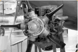
“RR Griffon 66” (E.V.)
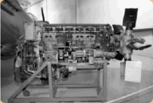
“View of the Griffon 66”
-This engine is a very correct cutaway, showing not previously known details.
-We come back to the Crecy engine because we found out some interesting details of it.
-It is a 12-cylinder upright V engine with turbocharging and gearbox.
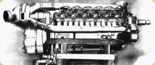
“Rare old photo of the Crecy”
-But its main characteristic was a two stroke engine and that it had sliding sleeves, which decreased the overall volume of the engine.
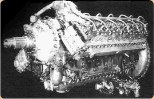
“View of the complete Crecy engine”
-But even more interesting is the actuation system of the sliding sleeves, totally different from the well-known Bristol “Hercules”, “Centaurus”, etc.
-The fact that the frontal area of the engine is smaller, can be seen in the below illustration in which the engine has shorter cylinders due to the absence of overhead valves and their spring and rocker boxes.
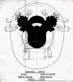
“Crecy front area”
-The performance of the sleeves is something difficult to understand if you don't pay close attention.
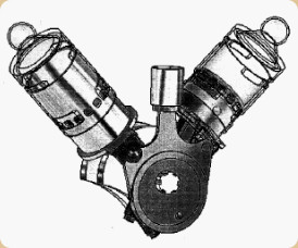
“The small central cylinder is fixed”
From Appendix 12: We knew that the development potential of the new Trent Turboprop (the 900 already flies with the Airbus A.-380) could exceed 100,000 lbf of thrust.
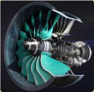
“The new Trent PGB”
-The new PGB is already underway with an important "Power Gear Box" to make a significant reduction of the PTO shaft (Power Take Off) before taking the huge turbofan (called Ultra Fan) of more than 3 meters in diameter .
“The gearbox is developed by Rolls-Royce Germany”
-As is well known, the tip of the UltraFan blades should not reach a peripheral speed equal to the speed of sound, which is why as the Fan diameter increases more and more, it is necessary to add a reduction.
-The shape of the fan blades and the large "rope" of the profile are striking. The materials are mixed carbon fiber and titanium.
-it is expected to be released around 2025.
-It is the new turbofan in the project called "Ultra-fan" with larger dimensions than those of the order of the Trent of the A-380. (Trent 900).
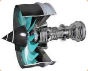
“Observe the left turn of the fan, typical British”
Engines of ROLLS - ROYCE
Modelo: ACCEL Yuasa electric (YUSA)
Electric
Cooling:
Power:
RPM:
Weight:
Model: AE-1107C “Liberty”
Arquitecture:
Compressor/s:
Combustion chambers:
Turbines:
Power / Thrust: / ---
Weight:
Model: AE-2100
Arquitecture:
Compressor/s:
Combustion chambers:
Turbines:
Power / Thrust: / ---
Weight:
Model: AE-3007
Arquitecture:
Compressor/s:
Combustion chambers:
Turbines:
Power / Thrust: / ---
Weight:
Model: AJ-65 (RA.1)
Arquitecture:
Compressor/s:
Combustion chambers:
Turbines:
Power / Thrust: / ---
Weight:
Model: Allison USA engines
Model: AS Viper (later Bristol and RR)
Arquitecture:
Compressor/s:
Combustion chambers:
Turbines:
Power / Thrust: / ---
Weight:
Model: Avon
Arquitecture:
Compressor/s:
Combustion chambers:
Turbines:
Power / Thrust: / ---
Weight:
Model: ”G” (Predecesor del Griffon)
Arquitecture:
Cooling:
Total Displacement:
Bore / Stroke: x
Power:
Weight:
Model: ”R”
Arquitecture:
Cooling:
Total Displacement:
Bore / Stroke: x
Power:
Weight:
Model: Buzzard
Arquitecture:
Cooling:
Total Displacement:
Bore / Stroke: x
Power:
Weight:
Model: Clyde
Arquitecture:
Compressor/s:
Combustion chambers:
Turbines:
Power / Thrust: / ---
Weight:
Model: Condor, I, II, III, IV and a Diesel
Arquitecture:
Cooling:
Total Displacement:
Bore / Stroke: x
Power:
Weight:
Model: Cont./RR, IO-360
Arquitecture:
Cooling:
Total Displacement:
Bore / Stroke: x
Power:
Weight:
Model: Cont./RR, IO-368
Arquitecture:
Cooling:
Total Displacement:
Bore / Stroke: x
Power:
Weight:
Model: Cont./RR, O-240
Arquitecture:
Cooling:
Total Displacement:
Bore / Stroke: x
Power:
Weight:
Model: Cont./RR, O-300
Arquitecture:
Cooling:
Total Displacement:
Bore / Stroke: x
Power:
Weight:
Model: Cont./RR. O-200
Arquitecture:
Cooling:
Total Displacement:
Bore / Stroke: x
Power:
Weight:
Model: Conway
Arquitecture:
Compressor/s:
Combustion chambers:
Turbines:
Power / Thrust: / ---
Weight:
Model: Crecy
Arquitecture:
Cooling:
Total Displacement:
Bore / Stroke: x
Power:
Weight:
Model: Dart
Arquitecture:
Compressor/s:
Combustion chambers:
Turbines:
Power / Thrust: / ---
Weight:
Model: Derwent 8
Arquitecture:
Compressor/s:
Combustion chambers:
Turbines:
Power / Thrust: / ---
Weight:
Model: Derwent 9
Arquitecture:
Compressor/s:
Combustion chambers:
Turbines:
Power / Thrust: / ---
Weight:
Model: Derwent I
Arquitecture:
Compressor/s:
Combustion chambers:
Turbines:
Power / Thrust: / ---
Weight:
Model: Derwent II
Arquitecture:
Compressor/s:
Combustion chambers:
Turbines:
Power / Thrust: / ---
Weight:
Model: Derwent III
Arquitecture:
Compressor/s:
Combustion chambers:
Turbines:
Power / Thrust: / ---
Weight:
Model: Derwent IV
Arquitecture:
Compressor/s:
Combustion chambers:
Turbines:
Power / Thrust: / ---
Weight:
Model: Derwent V
Arquitecture:
Compressor/s:
Combustion chambers:
Turbines:
Power / Thrust: / ---
Weight:
Model: Eagle, 12 in V, I-IX
Arquitecture:
Cooling:
Total Displacement:
Bore / Stroke: x
Power:
Weight:
Model: Eagle, 16 in X (XVI)
Arquitecture:
Cooling:
Total Displacement:
Bore / Stroke: x
Power:
Weight:
Model: Eagle, 22
Arquitecture:
Cooling:
Total Displacement:
Bore / Stroke: x
Power:
Weight:
Model: Eagle, 24 in H horiz.
Arquitecture:
Cooling:
Total Displacement:
Bore / Stroke: x
Power:
Weight:
Model: EJ-200
Arquitecture:
Compressor/s:
Combustion chambers:
Turbines:
Power / Thrust: / ---
Weight:
Model: Exe (Boreas)
Arquitecture:
Cooling:
Total Displacement:
Bore / Stroke:
Power:
Weight:
Model: F-10
Arquitecture:
Cooling:
Total Displacement:
Bore / Stroke: x
Power:
Weight:
Model: F-113 (Spey)
Arquitecture:
Compressor/s:
Combustion chambers:
Turbines:
Power / Thrust: / ---
Weight:
Model: F-126 (Tay)
Arquitecture:
Compressor/s:
Combustion chambers:
Turbines:
Power / Thrust: / ---
Weight:
Model: F-136
Arquitecture:
Compressor/s:
Combustion chambers:
Turbines:
Power / Thrust: / ---
Weight:
Model: F-137 (AE-3007)
Arquitecture:
Compressor/s:
Combustion chambers:
Turbines:
Power / Thrust: / ---
Weight:
Model: F-402 (Pegasus)
Arquitecture:
Compressor/s:
Combustion chambers:
Turbines:
Power / Thrust: / ---
Weight:
Model: F-405 (Adour)
Arquitecture:
Compressor/s:
Combustion chambers:
Turbines:
Power / Thrust: / ---
Weight:
Model: Falcon, I, II, III
Arquitecture:
Cooling:
Total Displacement:
Bore / Stroke: x
Power:
Weight:
Model: FS
Arquitecture:
Cooling:
Total Displacement:
Bore / Stroke: x
Power:
Weight:
Model: GEM series
Arquitecture:
Compressor/s:
Combustion chambers:
Turbines:
Power / Thrust: / ---
Weight:
Model: Gnome and all De Haviland engines
Model: Goshawk
Arquitecture:
Cooling:
Total Displacement:
Bore / Stroke: x
Power:
Weight:
Model: Griffon 101
Arquitecture:
Cooling:
Total Displacement:
Bore / Stroke: x
Power:
Weight:
Model: Griffon 102
Arquitecture:
Cooling:
Total Displacement:
Bore / Stroke: x
Power:
Weight:
Model: Griffon 121
Arquitecture:
Cooling:
Total Displacement:
Bore / Stroke: x
Power:
Weight:
Model: Griffon 126
Arquitecture:
Cooling:
Total Displacement:
Bore / Stroke: x
Power:
Weight:
Model: Griffon 130
Arquitecture:
Cooling:
Total Displacement:
Bore / Stroke: x
Power:
Weight:
Model: Griffon 26
Arquitecture:
Cooling:
Total Displacement:
Bore / Stroke: x
Power:
Weight:
Model: Griffon 35ML
Arquitecture:
Cooling:
Total Displacement:
Bore / Stroke: x
Power:
Weight:
Model: Griffon 57, 57A
Arquitecture:
Cooling:
Total Displacement:
Bore / Stroke:
Power:
Weight:
Model: Griffon 61
Arquitecture:
Cooling:
Total Displacement:
Bore / Stroke: x
Power:
Weight:
Model: Griffon 64
Arquitecture:
Cooling:
Total Displacement:
Bore / Stroke: x
Power:
Weight:
Model: Griffon 65
Arquitecture:
Cooling:
Total Displacement:
Bore / Stroke: x
Power:
Weight:
Model: Griffon 66
Arquitecture:
Cooling:
Total Displacement:
Bore / Stroke: x
Power:
Weight:
Model: Griffon 67
Arquitecture:
Cooling:
Total Displacement:
Bore / Stroke: x
Power:
Weight:
Model: Griffon 69
Arquitecture:
Cooling:
Total Displacement:
Bore / Stroke: x
Power:
Weight:
Model: Griffon 72
Arquitecture:
Cooling:
Total Displacement:
Bore / Stroke: x
Power:
Weight:
Model: Griffon 74
Arquitecture:
Cooling:
Total Displacement:
Bore / Stroke: x
Power:
Weight:
Model: Griffon 83
Arquitecture:
Cooling:
Total Displacement:
Bore / Stroke: x
Power:
Weight:
Model: Griffon 85
Arquitecture:
Cooling:
Total Displacement:
Bore / Stroke: x
Power:
Weight:
Model: Griffon 86
Arquitecture:
Cooling:
Total Displacement:
Bore / Stroke: x
Power:
Weight:
Model: Griffon 87
Arquitecture:
Cooling:
Total Displacement:
Bore / Stroke: x
Power:
Weight:
Model: Griffon 88
Arquitecture:
Cooling:
Total Displacement:
Bore / Stroke: x
Power:
Weight:
Model: Griffon 89
Arquitecture:
Cooling:
Total Displacement:
Bore / Stroke: x
Power:
Weight:
Model: Griffon 90
Arquitecture:
Cooling:
Total Displacement:
Bore / Stroke: x
Power:
Weight:
Model: Griffon I
Arquitecture:
Cooling:
Total Displacement:
Bore / Stroke: x
Power:
Weight:
Model: Griffon II
Arquitecture:
Cooling:
Total Displacement:
Bore / Stroke: x
Power:
Weight:
Model: Griffon III
Arquitecture:
Cooling:
Total Displacement:
Bore / Stroke:
Power:
Weight:
Model: Griffon IV
Arquitecture:
Cooling:
Total Displacement:
Bore / Stroke: x
Power:
Weight:
Model: Griffon V
Arquitecture:
Cooling:
Total Displacement:
Bore / Stroke: x
Power:
Weight:
Model: Griffon VI
Arquitecture:
Cooling:
Total Displacement:
Bore / Stroke: x
Power:
Weight:
Model: Hawk
Arquitecture:
Cooling:
Total Displacement:
Bore / Stroke: x
Power:
Weight:
Model: Hercules and all Bristol engines
Model: IAE V-2500
Arquitecture:
Compressor/s:
Combustion chambers:
Turbines:
Power / Thrust: / ---
Weight:
Model: J-99
Arquitecture:
Compressor/s:
Combustion chambers:
Turbines:
Power / Thrust: / ---
Weight:
Model: Kestrel
Arquitecture:
Cooling:
Total Displacement:
Bore / Stroke: x
Power:
Weight:
Model: KHD T-112
Arquitecture:
Compressor/s:
Combustion chambers:
Turbines:
Power / Thrust: / ---
Weight:
Model: Medway
Arquitecture:
Compressor/s:
Combustion chambers:
Turbines:
Power / Thrust: / ---
Weight:
Model: Merlin 100
Arquitecture:
Cooling:
Total Displacement:
Bore / Stroke:
Power:
Weight:
Model: Merlin 102
Arquitecture:
Cooling:
Total Displacement:
Bore / Stroke:
Power:
Weight:
Model: Merlin 113/114
Arquitecture:
Cooling:
Total Displacement:
Bore / Stroke: x
Power:
Weight:
Model: Merlin 130, 130/131, 130/134
Arquitecture:
Cooling:
Total Displacement:
Bore / Stroke: x
Power:
Weight:
Model: Merlin 140
Arquitecture:
Cooling:
Total Displacement:
Bore / Stroke: x
Power:
Weight:
Model: Merlin 21
Arquitecture:
Cooling:
Total Displacement:
Bore / Stroke: x
Power:
Weight:
Model: Merlin 22, 22A
Arquitecture:
Cooling:
Total Displacement:
Bore / Stroke: x
Power:
Weight:
Model: Merlin 224
Arquitecture:
Cooling:
Total Displacement:
Bore / Stroke: x
Power:
Weight:
Model: Merlin 225
Arquitecture:
Cooling:
Total Displacement:
Bore / Stroke: x
Power:
Weight:
Model: Merlin 23
Arquitecture:
Cooling:
Total Displacement:
Bore / Stroke:
Power:
Weight:
Model: Merlin 25
Arquitecture:
Cooling:
Total Displacement:
Bore / Stroke: x
Power:
Weight:
Model: Merlin 26
Arquitecture:
Cooling:
Total Displacement:
Bore / Stroke: x
Power:
Weight:
Model: Merlin 266
Arquitecture:
Cooling:
Total Displacement:
Bore / Stroke: x
Power:
Weight:
Model: Merlin 27
Arquitecture:
Cooling:
Total Displacement:
Bore / Stroke: x
Power:
Weight:
Model: Merlin 28
Arquitecture:
Cooling:
Total Displacement:
Bore / Stroke: x
Power:
Weight:
Model: Merlin 29
Arquitecture:
Cooling:
Total Displacement:
Bore / Stroke: x
Power:
Weight:
Model: Merlin 30
Arquitecture:
Cooling:
Total Displacement:
Bore / Stroke: x
Power:
Weight:
Model: Merlin 31
Arquitecture:
Cooling:
Total Displacement:
Bore / Stroke: x
Power:
Weight:
Model: Merlin 32
Arquitecture:
Cooling:
Total Displacement:
Bore / Stroke: x
Power:
Weight:
Model: Merlin 33
Arquitecture:
Cooling:
Total Displacement:
Bore / Stroke: x
Power:
Weight:
Model: Merlin 35
Arquitecture:
Cooling:
Total Displacement:
Bore / Stroke: x
Power:
Weight:
Model: Merlin 38
Arquitecture:
Cooling:
Total Displacement:
Bore / Stroke: x
Power:
Weight:
Model: Merlin 45, 45M
Arquitecture:
Cooling:
Total Displacement:
Bore / Stroke: x
Power:
Weight:
Model: Merlin 46
Arquitecture:
Cooling:
Total Displacement:
Bore / Stroke: x
Power:
Weight:
Model: Merlin 47
Arquitecture:
Cooling:
Total Displacement:
Bore / Stroke: x
Power:
Weight:
Model: Merlin 50, 50M
Arquitecture:
Cooling:
Total Displacement:
Bore / Stroke: x
Power:
Weight:
Model: Merlin 500, 500/20, 500/29, 500/45
Arquitecture:
Cooling:
Total Displacement:
Bore / Stroke: x
Power:
Weight:
Model: Merlin 501
Arquitecture:
Cooling:
Total Displacement:
Bore / Stroke: x
Power:
Weight:
Model: Merlin 55, 55M
Arquitecture:
Cooling:
Total Displacement:
Bore / Stroke: x
Power:
Weight:
Model: Merlin 60
Arquitecture:
Cooling:
Total Displacement:
Bore / Stroke: x
Power:
Weight:
Model: Merlin 604
Arquitecture:
Cooling:
Total Displacement:
Bore / Stroke: x
Power:
Weight:
Model: Merlin 61
Arquitecture:
Cooling:
Total Displacement:
Bore / Stroke: x
Power:
Weight:
Model: Merlin 62
Arquitecture:
Cooling:
Total Displacement:
Bore / Stroke: x
Power:
Weight:
Model: Merlin 620
Arquitecture:
Cooling:
Total Displacement:
Bore / Stroke: x
Power:
Weight:
Model: Merlin 621
Arquitecture:
Cooling:
Total Displacement:
Bore / Stroke: x
Power:
Weight:
Model: Merlin 63, 63A
Arquitecture:
Cooling:
Total Displacement:
Bore / Stroke: x
Power:
Weight:
Model: Merlin 64
Arquitecture:
Cooling:
Total Displacement:
Bore / Stroke: x
Power:
Weight:
Model: Merlin 65
Arquitecture:
Cooling:
Total Displacement:
Bore / Stroke: x
Power:
Weight:
Model: Merlin 66
Arquitecture:
Cooling:
Total Displacement:
Bore / Stroke: x
Power:
Weight:
Model: Merlin 67
Arquitecture:
Cooling:
Total Displacement:
Bore / Stroke: x
Power:
Weight:
Model: Merlin 68
Arquitecture:
Cooling:
Total Displacement:
Bore / Stroke: x
Power:
Weight:
Model: Merlin 69
Arquitecture:
Cooling:
Total Displacement:
Bore / Stroke: x
Power:
Weight:
Model: Merlin 70
Arquitecture:
Cooling:
Total Displacement:
Bore / Stroke: x
Power:
Weight:
Model: Merlin 71
Arquitecture:
Cooling:
Total Displacement:
Bore / Stroke: x
Power:
Weight:
Model: Merlin 72
Arquitecture:
Cooling:
Total Displacement:
Bore / Stroke: x
Power:
Weight:
Model: Merlin 73
Arquitecture:
Cooling:
Total Displacement:
Bore / Stroke: x
Power:
Weight:
Model: Merlin 76
Arquitecture:
Cooling:
Total Displacement:
Bore / Stroke: x
Power:
Weight:
Model: Merlin 77
Arquitecture:
Cooling:
Total Displacement:
Bore / Stroke: x
Power:
Weight:
Model: Merlin 85
Arquitecture:
Cooling:
Total Displacement:
Bore / Stroke: x
Power:
Weight:
Model: Merlin B
Arquitecture:
Cooling:
Total Displacement:
Bore / Stroke: x
Power:
Weight:
Model: Merlin C
Arquitecture:
Cooling:
Total Displacement:
Bore / Stroke: x
Power:
Weight:
Model: Merlin F
Arquitecture:
Cooling:
Total Displacement:
Bore / Stroke:
Power:
Weight:
Model: Merlin G
Arquitecture:
Cooling:
Total Displacement:
Bore / Stroke: x
Power:
Weight:
Model: Merlin I
Arquitecture:
Cooling:
Total Displacement:
Bore / Stroke: x
Power:
Weight:
Model: Merlin II
Arquitecture:
Cooling:
Total Displacement:
Bore / Stroke: x
Power:
Weight:
Model: Merlin III
Arquitecture:
Cooling:
Total Displacement:
Bore / Stroke: x
Power:
Weight:
Model: Merlin T-24
Arquitecture:
Cooling:
Total Displacement:
Bore / Stroke: x
Power:
Weight:
Model: Merlin VI
Arquitecture:
Cooling:
Total Displacement:
Bore / Stroke:
Power:
Weight:
Model: Merlin VIII
Arquitecture:
Cooling:
Total Displacement:
Bore / Stroke: x
Power:
Weight:
Model: Merlin X
Arquitecture:
Cooling:
Total Displacement:
Bore / Stroke: x
Power:
Weight:
Model: Merlin XII, /30
Arquitecture:
Cooling:
Total Displacement:
Bore / Stroke:
Power:
Weight:
Model: Merlin XIX
Arquitecture:
Cooling:
Total Displacement:
Bore / Stroke: x
Power:
Weight:
Model: Merlin XX
Model: Meteor
Arquitecture:
Cooling:
Total Displacement:
Bore / Stroke: x
Power:
Weight:
Model: Nene Mk.10
Arquitecture:
Compressor/s:
Combustion chambers:
Turbines:
Power / Thrust: / ---
Weight:
Model: Nene Mk.101
Arquitecture:
Compressor/s:
Combustion chambers:
Turbines:
Power / Thrust:
Weight:
Model: Nene Mk.102
Arquitecture:
Compressor/s:
Combustion chambers:
Turbines:
Power / Thrust:
Weight:
Model: Nene Mk.103
Arquitecture:
Compressor/s:
Combustion chambers:
Turbines:
Power / Thrust: / ---
Weight:
Model: Nene Mk.3
Arquitecture:
Compressor/s:
Combustion chambers:
Turbines:
Power / Thrust: / ---
Weight:
Model: Nene RN.1
Arquitecture:
Compressor/s:
Combustion chambers:
Turbines:
Power / Thrust: / ---
Weight:
Model: Nene RN.2
Arquitecture:
Compressor/s:
Combustion chambers:
Turbines:
Power / Thrust: / ---
Weight:
Model: Nene RN.6
Arquitecture:
Compressor/s:
Combustion chambers:
Turbines:
Power / Thrust: / ---
Weight:
Model: Nimbus and all Blackburn engines
Model: Olympus
Arquitecture:
Compressor/s:
Combustion chambers:
Turbines:
Power / Thrust: / ---
Weight:
Model: Pearl 15
Arquitecture:
Compressor/s:
Combustion chambers:
Turbines:
Power / Thrust: / ---
Weight:
Model: Pegasus (F-402)
Arquitecture:
Compressor/s:
Combustion chambers:
Turbines:
Power / Thrust: / ---
Weight:
Model: Pennine
Arquitecture:
Cooling:
Total Displacement:
Bore / Stroke: x
Power:
Weight:
Model: Peregrine
Arquitecture:
Cooling:
Total Displacement:
Bore / Stroke: x
Power:
Weight:
Model: PV-12
Arquitecture:
Cooling:
Total Displacement:
Bore / Stroke: x
Power:
Weight:
Model: RB-106
Arquitecture:
Compressor/s:
Combustion chambers:
Turbines:
Power / Thrust: / ---
Weight:
Model: RB-108
Arquitecture:
Compressor/s:
Combustion chambers:
Turbines:
Power / Thrust: / ---
Weight:
Model: RB-109
Arquitecture:
Compressor/s:
Combustion chambers:
Turbines:
Power / Thrust: / ---
Weight:
Model: RB-115
Arquitecture:
Compressor/s:
Combustion chambers:
Turbines:
Power / Thrust: / ---
Weight:
Model: RB-121
Arquitecture:
Compressor/s:
Combustion chambers:
Turbines:
Power / Thrust: / ---
Weight:
Model: RB-122
Arquitecture:
Compressor/s:
Combustion chambers:
Turbines:
Power / Thrust: / ---
Weight:
Model: RB-123
Arquitecture:
Compressor/s:
Combustion chambers:
Turbines:
Power / Thrust: / ---
Weight:
Model: RB-126
Arquitecture:
Compressor/s:
Combustion chambers:
Turbines:
Power / Thrust: / ---
Weight:
Model: RB-127
Arquitecture:
Compressor/s:
Combustion chambers:
Turbines:
Power / Thrust: / ---
Weight:
Model: RB-128
Arquitecture:
Compressor/s:
Combustion chambers:
Turbines:
Power / Thrust: / ---
Weight:
Model: RB-133
Arquitecture:
Compressor/s:
Combustion chambers:
Turbines:
Power / Thrust: / ---
Weight:
Model: RB-140
Arquitecture:
Compressor/s:
Combustion chambers:
Turbines:
Power / Thrust: / ---
Weight:
Model: RB-141 (Medway)
Arquitecture:
Compressor/s:
Combustion chambers:
Turbines:
Power / Thrust: / ---
Weight:
Model: RB-142
Arquitecture:
Compressor/s:
Combustion chambers:
Turbines:
Power / Thrust: / ---
Weight:
Model: RB-145
Arquitecture:
Compressor/s:
Combustion chambers:
Turbines:
Power / Thrust: / ---
Weight:
Model: RB-146
Arquitecture:
Compressor/s:
Combustion chambers:
Turbines:
Power / Thrust: / ---
Weight:
Model: RB-153
Arquitecture:
Compressor/s:
Combustion chambers:
Turbines:
Power / Thrust: / ---
Weight:
Model: RB-162
Arquitecture:
Compressor/s:
Combustion chambers:
Turbines:
Power / Thrust: / ---
Weight:
Model: RB-163 (Spey)
Arquitecture:
Compressor/s:
Combustion chambers:
Turbines:
Power / Thrust: / ---
Weight:
Model: RB-168 (Spey)
Arquitecture:
Compressor/s:
Combustion chambers:
Turbines:
Power / Thrust: / ---
Weight:
Model: RB-172
Arquitecture:
Compressor/s:
Combustion chambers:
Turbines:
Power / Thrust: / ---
Weight:
Model: RB-173
Arquitecture:
Compressor/s:
Combustion chambers:
Turbines:
Power / Thrust: / ---
Weight:
Model: RB-174
Arquitecture:
Compressor/s:
Combustion chambers:
Turbines:
Power / Thrust: / ---
Weight:
Model: RB-175
Arquitecture:
Compressor/s:
Combustion chambers:
Turbines:
Power / Thrust: / ---
Weight:
Model: RB-176
Arquitecture:
Compressor/s:
Combustion chambers:
Turbines:
Power / Thrust: / ---
Weight:
Model: RB-177
Arquitecture:
Compressor/s:
Combustion chambers:
Turbines:
Power / Thrust: / ---
Weight:
Model: RB-178
Arquitecture:
Compressor/s:
Combustion chambers:
Turbines:
Power / Thrust: / ---
Weight:
Model: RB-180
Arquitecture:
Compressor/s:
Combustion chambers:
Turbines:
Power / Thrust: / ---
Weight:
Model: RB-181
Arquitecture:
Compressor/s:
Combustion chambers:
Turbines:
Power / Thrust: / ---
Weight:
Model: RB-183 (Tay)
Arquitecture:
Compressor/s:
Combustion chambers:
Turbines:
Power / Thrust: / ---
Weight:
Model: RB-189
Arquitecture:
Compressor/s:
Combustion chambers:
Turbines:
Power / Thrust: / ---
Weight:
Model: RB-193
Arquitecture:
Compressor/s:
Combustion chambers:
Turbines:
Power / Thrust: / ---
Weight:
Model: RB-199 (Tornado A/C)
Arquitecture:
Compressor/s:
Combustion chambers:
Turbines:
Power / Thrust: / ---
Weight:
Model: RB-202
Arquitecture:
Compressor/s:
Combustion chambers:
Turbines:
Power / Thrust: / ---
Weight:
Model: RB-203 (Trent By-pass)
Arquitecture:
Compressor/s:
Combustion chambers:
Turbines:
Power / Thrust: / ---
Weight:
Model: RB-207
Arquitecture:
Compressor/s:
Combustion chambers:
Turbines:
Power / Thrust: / ---
Weight:
Model: RB-211
Arquitecture:
Compressor/s:
Combustion chambers:
Turbines:
Power / Thrust: / ---
Weight:
Model: RB-213
Arquitecture:
Compressor/s:
Combustion chambers:
Turbines:
Power / Thrust: / ---
Weight:
Model: RB-220
Arquitecture:
Compressor/s:
Combustion chambers:
Turbines:
Power / Thrust: / ---
Weight:
Model: RB-225
Arquitecture:
Compressor/s:
Combustion chambers:
Turbines:
Power / Thrust: / ---
Weight:
Model: RB-227
Arquitecture:
Compressor/s:
Combustion chambers:
Turbines:
Power / Thrust: / ---
Weight:
Model: RB-228
Arquitecture:
Compressor/s:
Combustion chambers:
Turbines:
Power / Thrust: / ---
Weight:
Model: RB-23
Arquitecture:
Compressor/s:
Combustion chambers:
Turbines:
Power / Thrust: / ---
Weight:
Model: RB-231
Arquitecture:
Compressor/s:
Combustion chambers:
Turbines:
Power / Thrust: / ---
Weight:
Model: RB-235
Arquitecture:
Compressor/s:
Combustion chambers:
Turbines:
Power / Thrust: / ---
Weight:
Model: RB-236
Arquitecture:
Compressor/s:
Combustion chambers:
Turbines:
Power / Thrust: / ---
Weight:
Model: RB-238
Arquitecture:
Compressor/s:
Combustion chambers:
Turbines:
Power / Thrust: / ---
Weight:
Model: RB-26
Arquitecture:
Compressor/s:
Combustion chambers:
Turbines:
Power / Thrust: / ---
Weight:
Model: RB-277
Arquitecture:
Compressor/s:
Combustion chambers:
Turbines:
Power / Thrust: / ---
Weight:
Model: RB-318
Arquitecture:
Compressor/s:
Combustion chambers:
Turbines:
Power / Thrust: / ---
Weight:
Model: RB-346
Arquitecture:
Compressor/s:
Combustion chambers:
Turbines:
Power / Thrust: / ---
Weight:
Model: RB-37
Arquitecture:
Compressor/s:
Combustion chambers:
Turbines:
Power / Thrust: / ---
Weight:
Model: RB-39
Arquitecture:
Compressor/s:
Combustion chambers:
Turbines:
Power / Thrust: / ---
Weight:
Model: RB-40
Arquitecture:
Compressor/s:
Combustion chambers:
Turbines:
Power / Thrust: / ---
Weight:
Model: RB-401
Arquitecture:
Compressor/s:
Combustion chambers:
Turbines:
Power / Thrust: / ---
Weight:
Model: RB-406
Arquitecture:
Compressor/s:
Combustion chambers:
Turbines:
Power / Thrust: / ---
Weight:
Model: RB-409
Arquitecture:
Compressor/s:
Combustion chambers:
Turbines:
Power / Thrust: / ---
Weight:
Model: RB-41
Arquitecture:
Compressor/s:
Combustion chambers:
Turbines:
Power / Thrust: / ---
Weight:
Model: RB-410
Arquitecture:
Compressor/s:
Combustion chambers:
Turbines:
Power / Thrust: / ---
Weight:
Model: RB-422
Arquitecture:
Compressor/s:
Combustion chambers:
Turbines:
Power / Thrust: / ---
Weight:
Model: RB-43
Arquitecture:
Compressor/s:
Combustion chambers:
Turbines:
Power / Thrust: / ---
Weight:
Model: RB-431
Arquitecture:
Compressor/s:
Combustion chambers:
Turbines:
Power / Thrust: / ---
Weight:
Model: RB-432
Arquitecture:
Compressor/s:
Combustion chambers:
Turbines:
Power / Thrust: / ---
Weight:
Model: RB-44
Arquitecture:
Compressor/s:
Combustion chambers:
Turbines:
Power / Thrust: / ---
Weight:
Model: RB-50
Arquitecture:
Compressor/s:
Combustion chambers:
Turbines:
Power / Thrust: / ---
Weight:
Model: RB-508
Arquitecture:
Compressor/s:
Combustion chambers:
Turbines:
Power / Thrust: / ---
Weight:
Model: RB-509
Arquitecture:
Compressor/s:
Combustion chambers:
Turbines:
Power / Thrust: / ---
Weight:
Model: RB-524
Arquitecture:
Compressor/s:
Combustion chambers:
Turbines:
Power / Thrust: / ---
Weight:
Model: RB-529
Arquitecture:
Compressor/s:
Combustion chambers:
Turbines:
Power / Thrust: / ---
Weight:
Model: RB-53
Arquitecture:
Compressor/s:
Combustion chambers:
Turbines:
Power / Thrust: / ---
Weight:
Model: RB-533
Arquitecture:
Compressor/s:
Combustion chambers:
Turbines:
Power / Thrust: / ---
Weight:
Model: RB-535
Arquitecture:
Compressor/s:
Combustion chambers:
Turbines:
Power / Thrust: / ---
Weight:
Model: RB-543
Arquitecture:
Compressor/s:
Combustion chambers:
Turbines:
Power / Thrust: / ---
Weight:
Model: RB-545, rocket engine augmented with air
Arquitecture:
Chambers:
Fuels:
Feed System:
Ignition:
Thrust:
Weight:
Model: RB-549
Arquitecture:
Compressor/s:
Combustion chambers:
Turbines:
Power / Thrust: / ---
Weight:
Model: RB-550
Arquitecture:
Compressor/s:
Combustion chambers:
Turbines:
Power / Thrust: / ---
Weight:
Model: RB-553
Arquitecture:
Compressor/s:
Combustion chambers:
Turbines:
Power / Thrust: / ---
Weight:
Model: RB-566
Arquitecture:
Compressor/s:
Combustion chambers:
Turbines:
Power / Thrust: / ---
Weight:
Model: RB-571
Arquitecture:
Compressor/s:
Combustion chambers:
Turbines:
Power / Thrust: / ---
Weight:
Model: RB-578
Arquitecture:
Compressor/s:
Combustion chambers:
Turbines:
Power / Thrust: / ---
Weight:
Model: RB-580
Arquitecture:
Compressor/s:
Combustion chambers:
Turbines:
Power / Thrust: / ---
Weight:
Model: RB-77
Arquitecture:
Compressor/s:
Combustion chambers:
Turbines:
Power / Thrust: / ---
Weight:
Model: RB-78
Arquitecture:
Compressor/s:
Combustion chambers:
Turbines:
Power / Thrust: / ---
Weight:
Model: RB-80
Arquitecture:
Compressor/s:
Combustion chambers:
Turbines:
Power / Thrust: / ---
Weight:
Model: RB-82
Arquitecture:
Compressor/s:
Combustion chambers:
Turbines:
Power / Thrust: / ---
Weight:
Model: RB-90
Arquitecture:
Compressor/s:
Combustion chambers:
Turbines:
Power / Thrust: / ---
Weight:
Model: RB-93
Arquitecture:
Compressor/s:
Combustion chambers:
Turbines:
Power / Thrust: / ---
Weight:
Model: RJ-500
Arquitecture:
Compressor/s:
Combustion chambers:
Turbines:
Power / Thrust: / ---
Weight:
Model: RR-605
Arquitecture:
Compressor/s:
Combustion chambers:
Turbines:
Power / Thrust: / ---
Weight:
Model: RR/Allison 501 (T56)
Arquitecture:
Compressor/s:
Combustion chambers:
Turbines:
Power / Thrust: / ---
Weight:
Model: RR/Allison TF-401
Arquitecture:
Compressor/s:
Combustion chambers:
Turbines:
Power / Thrust: / ---
Weight:
Model: RZ-2 rocket engine
Arquitecture:
Chambers:
Fuels:
Feed System:
Ignition:
Thrust:
Weight:
Model: RZ-20 rocket engine
Arquitecture:
Chambers:
Fuels:
Feed System:
Ignition:
Thrust:
Weight:
Model: Sea Merlin
Arquitecture:
Cooling:
Total Displacement:
Bore / Stroke: x
Power:
Weight:
Model: Soar
Arquitecture:
Compressor/s:
Combustion chambers:
Turbines:
Power / Thrust: / ---
Weight:
Model: Spey
Arquitecture:
Compressor/s:
Combustion chambers:
Turbines:
Power / Thrust: / ---
Weight:
Model: Stentor (from Bristol)
Arquitecture:
Compressor/s:
Combustion chambers:
Turbines:
Power / Thrust: / ---
Weight:
Model: T-406
Arquitecture:
Compressor/s:
Combustion chambers:
Turbines:
Power / Thrust: / ---
Weight:
Model: T-501
Arquitecture:
Compressor/s:
Combustion chambers:
Turbines:
Power / Thrust: / ---
Weight:
Model: T-56
Arquitecture:
Compressor/s:
Combustion chambers:
Turbines:
Power / Thrust: / ---
Weight:
Model: T-68
Arquitecture:
Compressor/s:
Combustion chambers:
Turbines:
Power / Thrust: / ---
Weight:
Model: T-800
Arquitecture:
Compressor/s:
Combustion chambers:
Turbines:
Power / Thrust: / ---
Weight:
Model: Tay
Arquitecture:
Compressor/s:
Combustion chambers:
Turbines:
Power / Thrust: / ---
Weight:
Model: Trent 1000
Arquitecture:
Compressor/s:
Combustion chambers:
Turbines:
Power / Thrust: / ---
Weight:
Model: Trent 1700
Arquitecture:
Compressor/s:
Combustion chambers:
Turbines:
Power / Thrust: / ---
Weight:
Model: Trent 500
Arquitecture:
Compressor/s:
Combustion chambers:
Turbines:
Power / Thrust: / ---
Weight:
Model: Trent 600 (1)
Arquitecture:
Compressor/s:
Combustion chambers:
Turbines:
Power / Thrust:
Weight:
Model: Trent 600 (2)
Arquitecture:
Compressor/s:
Combustion chambers:
Turbines:
Power / Thrust: / ---
Weight:
Model: Trent 700
Arquitecture:
Compressor/s:
Combustion chambers:
Turbines:
Power / Thrust: / ---
Weight:
Model: Trent 7000
Arquitecture:
Compressor/s:
Combustion chambers:
Turbines:
Power / Thrust: / ---
Weight:
Model: Trent 800
Arquitecture:
Compressor/s:
Combustion chambers:
Turbines:
Power / Thrust: / ---
Weight:
Model: Trent 900
Arquitecture:
Compressor/s:
Combustion chambers:
Turbines:
Power / Thrust: / ---
Weight:
Model: Trent Advance
Arquitecture:
Compressor/s:
Combustion chambers:
Turbines:
Power / Thrust: / ---
Weight:
Model: Trent By-pass
Arquitecture:
Compressor/s:
Combustion chambers:
Turbines:
Power / Thrust: / ---
Weight:
Model: Trent turbohelice
Arquitecture:
Compressor/s:
Combustion chambers:
Turbines:
Power / Thrust: / ---
Weight:
Model: Trent XWB
Arquitecture:
Compressor/s:
Combustion chambers:
Turbines:
Power / Thrust: / ---
Weight:
Model: Trent-PGB UltraFan
Arquitecture:
Compressor/s:
Combustion chambers:
Turbines:
Power / Thrust: / ---
Weight:
Model: Tweed (AJ-25 ó AP-25)
Arquitecture:
Compressor/s:
Combustion chambers:
Turbines:
Power / Thrust: / ---
Weight:
Model: Tyne
Arquitecture:
Compressor/s:
Combustion chambers:
Turbines:
Power / Thrust: / ---
Weight:
Model: Vulture, I, II, II, IV, V
Arquitecture:
Cooling:
Total Displacement:
Bore / Stroke: x
Power:
Weight:
Model: Welland (RB-23)
Arquitecture:
Compressor/s:
Combustion chambers:
Turbines:
Power / Thrust: / ---
Weight:
Model: XG-40
Arquitecture:
Compressor/s:
Combustion chambers:
Turbines:
Power / Thrust: / ---
Weight:
Model: XV-99
Arquitecture:
Compressor/s:
Combustion chambers:
Turbines:
Power / Thrust: / ---
Weight:
