

Updated: 16-Jul-2021
The Metropolitan Vickers Electric Co., was not exactly an aeronautical industry, but it did have a lot of experience in steam turbines that drove electric generators.
-This company was commissioned to develop gas turbines, officially from RAE (Royal Aircraft Establishment) based on the studies of Whittle, Griffith and Hayne. The RAE “Freda” compressor was the basis for these engines.
-The Metropolitan Vickers was colloquially known as "Metrovick" and so were its turbines.
-The factory was installed in Manchester but the central offices were in London.
-The first engine to run was during World War II.
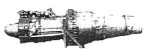
“First Metrovick”
“First F2”
-It started with the D-II in 1941, an engine that had an axial compressor.
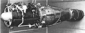
-This engine was abandoned in favor of the F2/1 and it was the first British axial compressor engine to fly. It did it first on a Lancaster and atomically on a Gloster Meteor.
“F2/1”
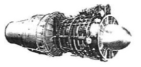
-It was followed by the F2/2.
“F2/2”
-These gave way to an induced flow engine try-out, the F2/3, according to the following scheme.
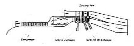
“F2/3”
-The F2/3 was later named F3. From 1943.
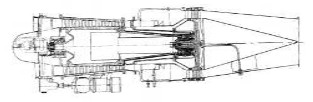
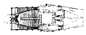
-The F3 is a by-pass engine with fans driven by free turbines at the outlet of the exhausts (see another recent example in the American General Electric chapter, decades later, with the same formula).
“F3”
-The F2/4 continued with the basic approach of the F2. In fact the number after the slash refers to the series.
“F2/4”
-Between the F2 series 1 and 4 we can notice the following differences:
| 1 | 4 | |
|---|---|---|
| Thrust: | 1800 lbf | 3500 lbf |
| Weight: | 1525 lbs | 1750 lbs |
| Diameter: | 33 pulgadas | 38 pulgadas |
| Length: | 10,8 pies | 13,3 pies |
-We see clearly that with few differences in size, the power has almost doubled.
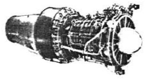
-The F2/4 series achieved 3,500 lbf of thrust at 7,700 rpm since it was an engine with a long 10-stage axial compressor and an annular chamber.
-As a curiosity, at the Manchester Museum there are several of these engines. Apart from the reference they had a proper name such as:
-The F2/1 was called “Freda”.
-The F2/4 was “Beryl”.
-The F3, due to its characteristics, received the name "Augmenter-Ducted Fan".
-And the B-10, that of "Betty". Without further information on this one.
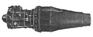
“F5”
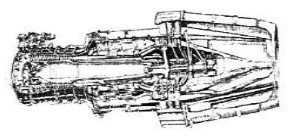
-In 1945, the F5 had an unducted fan, that is, propellers in sight, which was recently presented as a "Prop Fan" by Russians and Americans.
-Inside there were contra-rotating turbines that had propeller blades on their periphery.
“F9”
-What was known as the F9 in 1946 was the basis of the later "Sapphire" engines by Armstrong Siddeley that continued with this design from 1948.
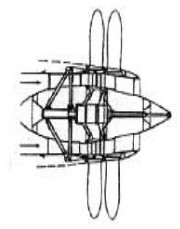
-Below we show the Metrovicks Beryl in double installation.
“Beryl double assembly"
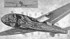
“Jet plane appeared in Flight magazine”
-In April 1942 a reproduction of a future airplane devised by Flight magazine carrying a "thermo-propellant" engine appears in the Spanish magazine "Revista de Aeronáutica". By its shape it is clearly a Metrovick.
From Appendix 6: When these engines appeared, known by the reduced name of “Metrovick”, they presented formulas that decades later would be adopted by other brands.
-For example the F3 (see also the main text) already had turbofans and aft-fans that we would later see in the GE CJ-805-23 of the Convair Coronado aircraft.
“F3 Nozzle and Bypass”
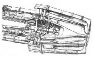
“Metrovick F3 aft-fan details”
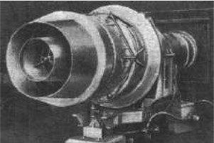
-Another spectacular design was the F5, existing in 1946 and that already had an UDF (Unducted Fan) that we would see several decades after its release, for example in the GE-36 UDF, or in several Russian examples.
-At the rear the F.5 had two contra-rotating propellers that acted as the F3's after-fan but without being channeled into a duct.
-We now have some recently obtained illustrations from a publication of the time. This engine allowed flying at 400 mph at an altitude of 20,000 ft. It gave about 4,710 lbf of thrust.
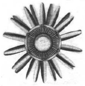
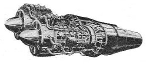
“View through the exhaust nozzle”
-The above illustration is interesting because it shows the contra-rotating multi-bladed propellers and in the center the turbines that drive them.
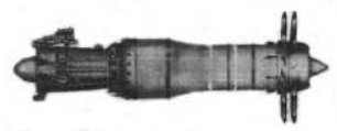
“Full F.5 photo”
Engines of METROPOLITAN VICKERS
Model: B-10 “Betty”
Arquitecture:
Compressor/s:
Combustion chambers:
Turbines:
Power / Thrust: / ---
Weight:
Model: Double Beryl
Arquitecture:
Compressor/s:
Combustion chambers:
Turbines:
Power / Thrust: / ---
Weight:
Model: F-1
Arquitecture:
Compressor/s:
Combustion chambers:
Turbines:
Power / Thrust: / ---
Weight:
Model: F-2 “Freda”
Arquitecture:
Compressor/s:
Combustion chambers:
Turbines:
Power / Thrust: / ---
Weight:
Model: F-2/2
Arquitecture:
Compressor/s:
Combustion chambers:
Turbines:
Power / Thrust: / ---
Weight:
Model: F-2/3 turbofan
Arquitecture:
Compressor/s:
Combustion chambers:
Turbines:
Power / Thrust: / ---
Weight:
Model: F-2/4 “Beryl”
Arquitecture:
Compressor/s:
Combustion chambers:
Turbines:
Power / Thrust: / ---
Weight:
Model: F-3 After-fan
Arquitecture:
Compressor/s:
Combustion chambers:
Turbines:
Power / Thrust: / ---
Weight:
Model: F-5 Prop-fan
Arquitecture:
Compressor/s:
Combustion chambers:
Turbines:
Power / Thrust: / ---
Weight:
Model: F-9 “Sapphire”
Arquitecture:
Compressor/s:
Combustion chambers:
Turbines:
Power / Thrust: / ---
Weight: