

Updated: 16-Apr-2021
Around 1917, the engineer Henri Mélot (like O. Morize) started work on ramjets to obtain a thrust lift for airplanes.
“Mélot's design”
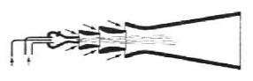
-It consisted of a combustion chamber in which an air and a fuel duct converged. The ignition was also planned for it.
-The main idea was to increase the mass of the exhaust gases -and consequently the thrust-, making them discharge onto several cascading venturis and in which a sufficient depression was created to suck and influence the existing air outside.
-In 1920 Mélot had patented a device that had multiple nozzles that were added to the outlet of a combustion chamber.
“Mélot's nozzle system”
-The contraption was known as "Mélot's Horn". Previously, during WWI he had made it available to the military authorities, who presumably made the pertinent tests and whose investigations were inconclusive and the engine discontinued.
-The principle was that of a thrust augmenter, taking full advantage of the performance of the generated combustion.
-At the Le Bourget Air and Space Museum there is a Mélot engine that was built in 1922.
“The Mélot engine at the MAE”
-There is a nice piece for teaching, with the Morize principle and possibly of Mélot himself at the MAE Engine Reserve Stock.
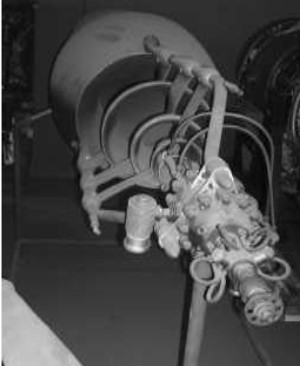
“Mélot multiple nozzle”
-By the main text we can see the annular rings allowing and adding air flow that, through the Ram-effect, increase their speed, and produces thrust.
-Later, in 1927, it was tested by two American researchers (Jacobs and Shoemaker) from the Langley Memorial Aeronautical Laboratory.
-It was studied to what extent the augmenter increased the thrust of the main engine.
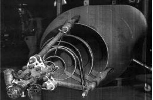
-The apparatus below was used, copying as much as possible the idea of Mélot.
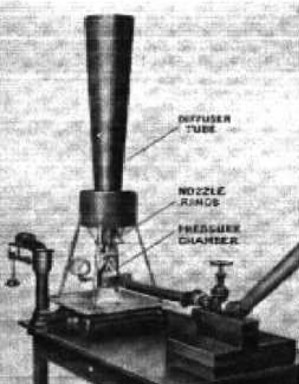
“Test in the USA”
-The engine was upside down on a scale. A combustion chamber resting on three rings and this all together on the diffuser nozzle.
-Instead of burning fuel, only compressed air was introduced to observe the increase that was taking place.
-One of the reasons for poor performance was that the mix did not have adequate compression in the chamber.
-Between 1922 and 1925 Mr. F. Mélot presented a double-acting, free-piston, double-stroke gas generator with the aim that the gases burned under pressure would affect the "propellant nozzles".
“Project of an experimental airplane with two Mélot engines” (PiP=ps)
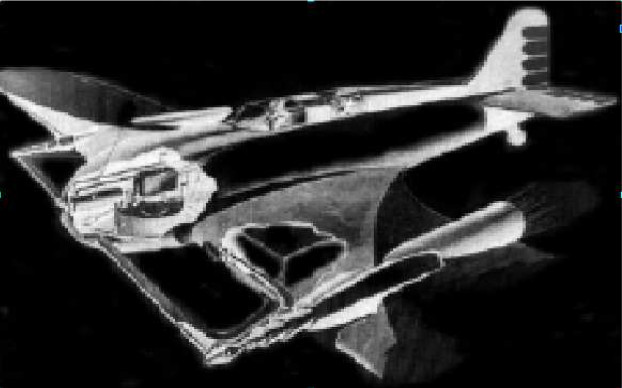
From Appendix 6: We now have another project from the 1930's of a twin engine airplane using two continuous combustion engines and Mélot augmenters.
-On Payen's page, we located an airplane project with his characteristic design from this exceptional engineer who also incorporated a type of ramjet that was designed by Mélot (see).
-The planned engine is possibly the prototype that is kept in the Mae Engine Reserve store.
-A model airplane with a piston engine, can be seen in the prototype room of the Le Bourget Air Museum. These aircraft used linear, opposed, radial piston engines, and more recently smaller Turbomeca turbines.
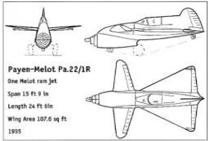
“The Payen aircraft with Mélot engine”
-Lately we received some old illustrations of the Mélot engine with augmenter.
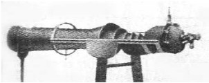
“Aspect of the Mélot in test stage"
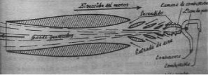
"And one more schematic drawing of the Mélot engine”
-It seems that consumption was going to be high and that its efficiency would not be until it reached high speeds.
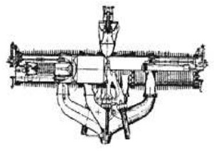
“Mélot gas generator”
-During the publication there are several gas generators of this type -or principle-: Lutz, Pescara, etc.
"Coupling of both devices"
-Finally we see the assembly of both concepts, the free piston engine and the device called Mélot's Horn.
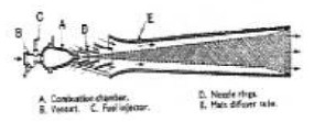
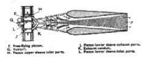
From Appendix 12: Inside a Mélot “Horn” we can see the flame tube where the air that enters through the central part is used for combustion -primary air- and that which passes through the periphery of the chamber is used to center the flame and to expand and generate propulsion -secondary air-.
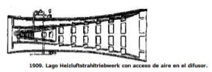
“Flame tube of a Mélot Horn”
Engines of MELOT
Model: free-piston gas generator
Arquitecture:
Chambers:
Fuels:
Feed System:
Ignition:
Thrust:
Weight:
Model: Melot "horns"
Arquitecture:
Chambers:
Fuels:
Feed System:
Ignition:
Thrust:
Weight:
"Mélot engine at the MAE"