

Updated: 13-Jun-2022
In 1946, Russian designer Vladimir A. Dobrynin made a 2,200 CV engine known as the VD-251 that was liquid cooled and had twelve cylinders in V.
-Being in the OKB Mikulin, he participated in the M-250 design together with Skuba Chevskyi. It was a radial with 6 blocks of four cylinders, 24 in total.
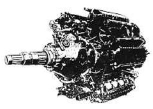
"Dobrynin M-250"
-Dobrynin developed the M-250 engine continuing with the VD-3 from 1945 derived from the M-250.
-The VD-3TK reached 3,500 CV. It was known as the M-251TK, and had 24 cylinders with turbochargers.
-VD-4 was a logical development from the VD-3TK, with
the VD-4TK (M-253K) reaching at 4,500 CV.
-Curiously it is claimed that the M-250's specific consumption was 165 grams x CV x Hr., When by the time, even decades later the "standard" consumption was 250 gr. x CV x Hr.
-We see the installation on board an aircraft, with turbocharger and its distribution.
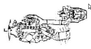
"M-250 Power train"
-The Dobrynin design office passed to Koliesov in 1955. Shortly before this fact he designed the VD-7, a powerful engine of almost 25,000 lbs. of thrust.
-There were other variants (-B, -F, -M, -P and M-2). With afterburner the power went to 36,000 lbs.
-VD-5 and VD-9 are also Dobrynin engines.
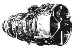
"DV-7”(VD-7)
From Appendix 9: Designer V. Drobynin's Technical Office (OKB-36) was little known but inspired high-performance engines with great powers.
-The VD-3 was also the M-250. As the VD-3TK was the M-251TK (TK is for the turbocharger).
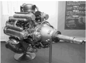
"VD-4K (M-253K)"
-The VD-4K is a complex and powerful engine, from 3,800 to 4,300 CV. It has six radially arranged blocks of 4 cylinders each. It is a Compound engine whose turbines, driven by the exhaust, add their power to the central shaft of the engine.
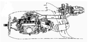
"Schematic diagram with turbocharger"
-The turbocharger is superimposed on top behind the main engine.
-The turbines between each two cylinder blocks are the "Compounds".
-The VD-5 was mounted on the Myasischev M-4. Without more information.
-The VD-5 was a turbine, but the most common Dobrynin turbine engine was the VD-7 and its variants such as the VD-7-BA (RD-7M2). Or the VD-9 on the Tu-106.
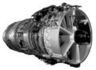
"Dobrynin VD-7B"
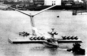
"Ten VD-7 engines on an Ekranoplane"
-The MB-100 was a horizontal-X piston engine, built by coupling two M-103s. It was a Dobrynin design and the engine gave 2,400 CV.
Engines of DOBRYNIN
Model: M-103
Arquitecture:
Cooling:
Total Displacement:
Bore / Stroke: x
Power: @ rpm
Weight:
Model: M-250 (VD-3)
Arquitecture: 24-cylinder Radial
Cooling:
Total Displacement:
Bore / Stroke:
Power:
Weight:
"Dobrynin M-250"
Model: M-251TK (VD-3Tk)
Arquitecture: 24-cylinder
Cooling:
Total Displacement:
Bore / Stroke:
Power: 3500 CV
Weight:
With turbocharger.
Model: M-253K (VD-4TK)
Arquitecture: 24-cylinder Radial
Cooling:
Total Displacement:
Bore / Stroke:
Power: 4500 CV
Weight:
It has six radially arranged blocks of 4 cylinders each. Compound engine
"Dobrynin VD-4K (M-253K)"
Model: MB-100
Arquitecture: X-engine
Cooling:
Total Displacement:
Bore / Stroke:
Power: 2400 CV @ rpm
Weight:
Model: VD-251
Arquitecture: 12-cylinder V-Engine
Cooling:
Total Displacement:
Bore / Stroke:
Power: 2200 CV
Weight:
Model: VD-5
Arquitecture:
Compressor/s:
Combustion chambers:
Turbines:
Power / Thrust:
Weight:
Model: VD-7 (Koliesov)
Arquitecture: Turbojet
Compressor/s:
Combustion chambers:
Turbines:
Power / Thrust: --- / 25000 Lbf
Weight:
With afterburner the power went to 36,000 lbs.
"Dobrynin VD-7B"
Model: VD-9
Arquitecture:
Compressor/s:
Combustion chambers:
Turbines:
Power / Thrust:
Weight: