

Updated: 30-Mar-2021
Hugo Junkers was the architect of a large aeronautical industry that included the construction of excellent aircraft and engines. Starting first with industrial and marine engines.
“Hugo Junkers”
-Born in 1859 in a family in the Rhineland. He died in 1935.
-He received a good training at polytechnic universities, and was vital and active. He worked in several factories that constructed machinery and gas engines.
-From 1897, he was offered a professorship at the Aachen Technical University, lecturing and researching until 1912.
-In 1895 he registered his company as “Junkers & Co.” and in 1913 he started manufacturing engines in Magdenburg.
-The gas heater he built had commercialization difficulties, since it was on the wall, when the stoves in general were standing on the floor. Its full acceptance took decades.
![]()
“Junkers logo”
-During these years he manufactured industrial gas and heavy oil engines such as the M-11 to M27, the MO-3, MO-8, HK-100, the 2.7 l, as well as a line of compressors, etc. His engines were built under license.
-The new Fo.1 was made with the intention of testing it on a plane in the year 1916, although it failed.
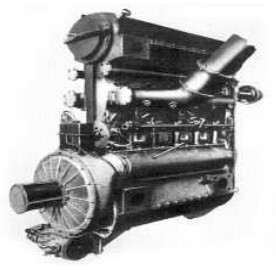
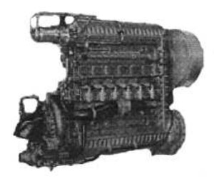
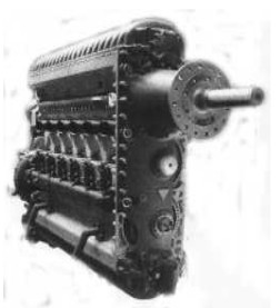
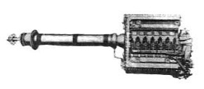
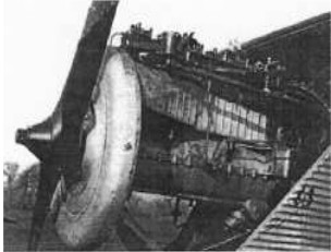
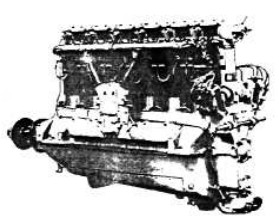
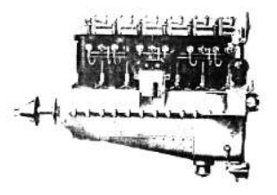
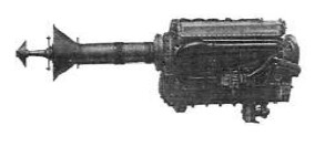
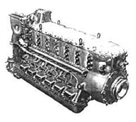
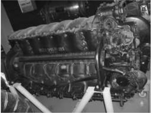
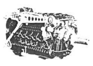
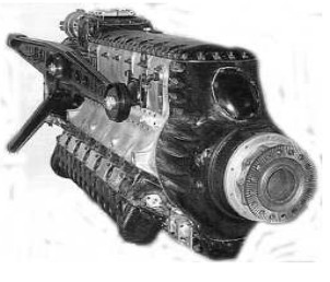
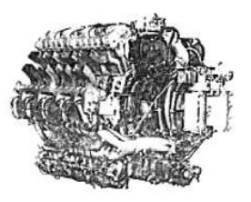
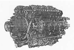
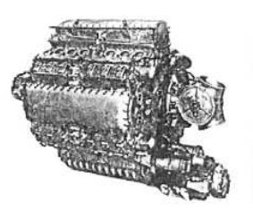
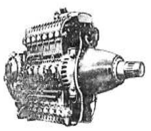
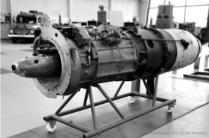
-The Fo.2 was a six-cylinder with two opposed pistons in each of them, with two synchronized crankshafts at the ends, a formula that was tested in the previous Mo.3 and Fo1.
“Junkers Fo.2”
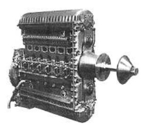
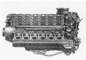
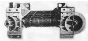
“Fo.2, rear view”
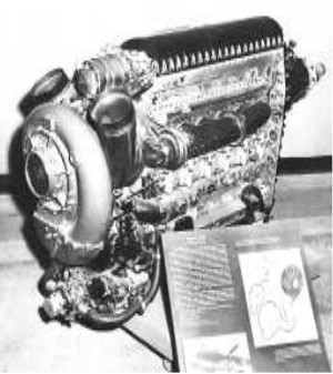
-The Fo.2 is developed around 1920, with a 2-stroke cycle giving 500 CV, It was Junkers' first aviation engine with opposed pistons, and with the cylinders in a horizontal position. It was the basis for another range of diesel engines of this type, which changed to the vertical position with the Fo.3 in 1926.
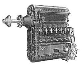
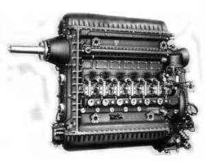
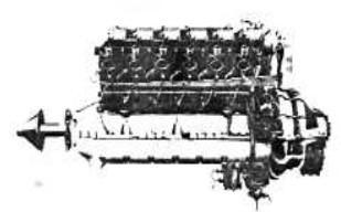
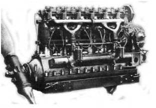
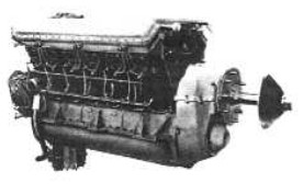
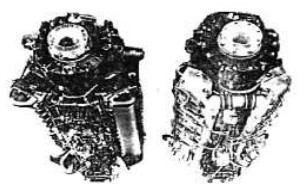
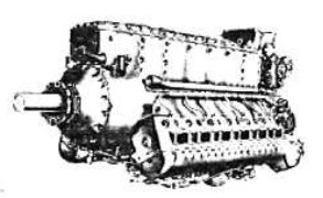
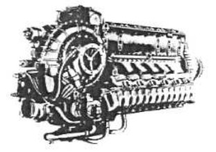
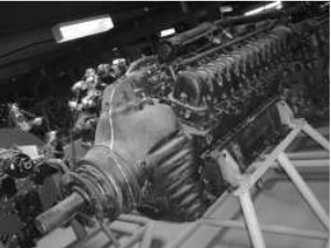
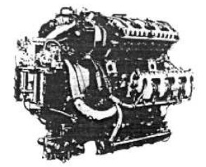
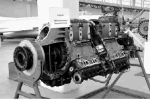
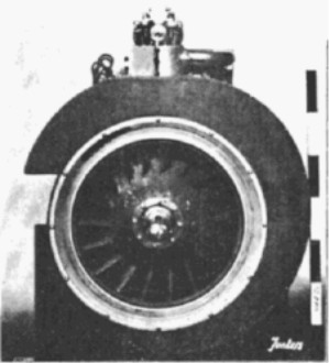
-The Fo.3 was never used in aviation, it is considered experimental.
“Junkers Fo.3, rear view”
-The Fo.3 had 2 crankshafts as well, and in one of the gears of the front train there was the extension for the propeller shaft.
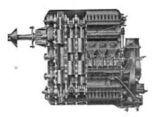
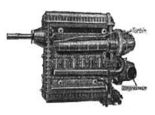
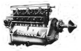
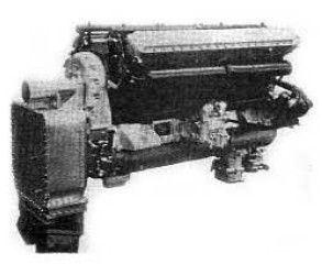
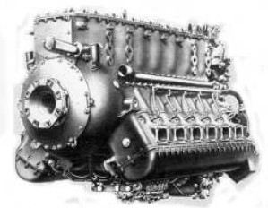
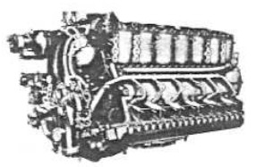
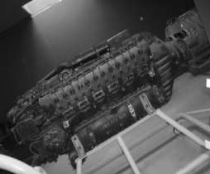
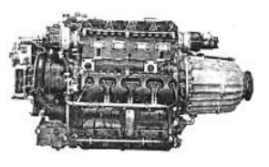
“Junkers Fo.4”
-The piston sleeves were extraordinarily long, with ports on each side, at the end of the piston stroke, the intake on one side and the exhaust on the other.
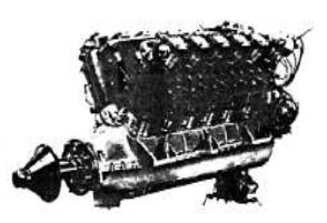
-Fo.3 gave 850 CV, while the Fo.4, which was very similar in general approach, gave 750 CV. The latter was the basis for the Jumo 4 and Jumo 204.
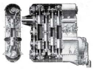
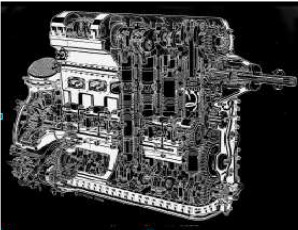
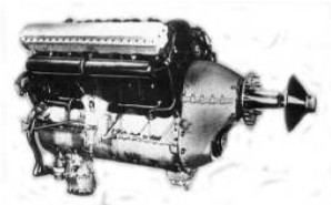
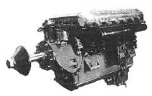
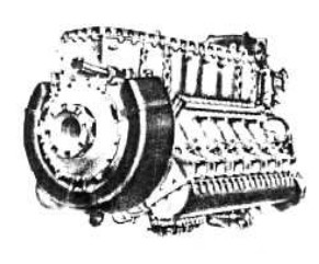
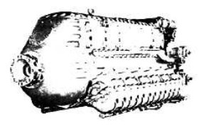
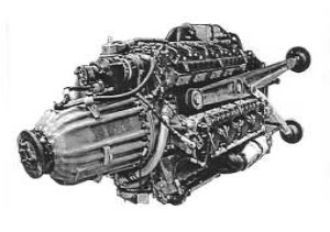
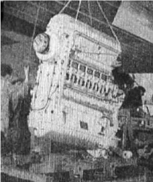
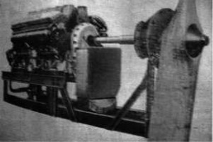
“Jumo 4, cutaway half”
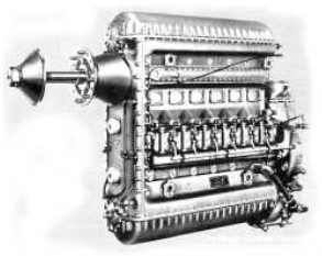
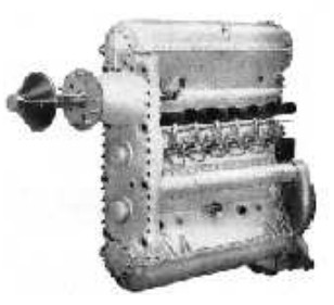
“Jumo 4”
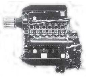
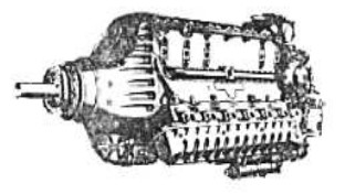
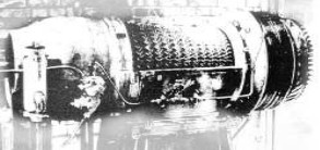
-In 1931 this engine gave way to the Jumo 204, with very clean lines. It was intensely tested on the Junkers F-24 aircraft.
“Jumo 204, cutaway”
-We see the front gears and how the propeller is coupled to the second upper one. The supercharger is attached to the rear of the lower crankshaft, to "force" the cylinder "sweeps". The Fo.4 flew on Lufthansa airliners, being the first Diesel engine to do so. Later it would be renamed Jumo 204.
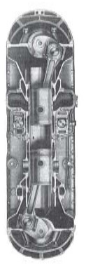
“Jumo 4, front cutaway”
“Jumo 204”
-In 1935, English Napier made a version of this engine as Napier "Culverin" with 720 CV.
“Napier Culverin”
-There is a Junkers model F2/601 at the Munich Museum. This supercharged Diesel engine with horizontally opposed pistons was built in April 1936.
“F2 / 601”
-The Junkers 5 (sometimes V), has been built in series A, B and C. They were smaller than the 204, and gave 405 CV.
-The Junkers 5 would give rise to the 205 series, from A to M and T. They delivered up to 650 CV in the D series.
“Jumo 5”
-The Jumo 5 engines were from 1932, and they changed to Jumo 205 in 1934. We can see that in the illustration the propeller is attached to the central gear. This is another capacity of this type of "Cutlass" engines (see Napier) in the 205 D version. So did the French company "Lilloise" in Lille.
“205C”
-They had supercharger and turbocharger in series. The latter was driven by the exhaust gases then passing the air to the mechanical second one, which these engines normally had, just below it. And from there the air went to the cylinders.
“205T”
-The 205 D version was liquid cooled, using “Glysantine” (a glycol refrigerant = water-alcohol).
-A small scheme for the T-version supercharging system is represented below.
“205T supercharging outline”
“205D” (PiP)
-Above we offer a beautiful drawing by technical artist Lyndon Jones, cited in another occasion in this publication. It allows us to see more construction details of these Diesel engines.
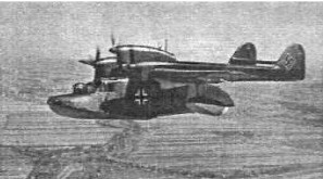
“On a flying boat”
-The Junkers Diesel engines were specially installed on patrol flying-boats, and rescue-aircraft on the Atlantic.
-As these engines consumed diesel oil, just like submarine engines, these aircraft could be supplied from these submarines or mother vessels, offshore.
“Junkers Jumo 205 in Brussels”
“Jumo 205”
-In the picture of the engine at the Brussels Museum we see the central output transmission for the propeller, while the propeller output shown in the picture below it was the most widespread. They were from DO-18, DO-26, etc.
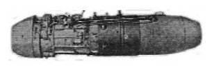
-The 206 was made with the intention of replacing the 204 and was based on the 205. This engine is from the year 1940 and was planned to reach 1,000 CV. It had no practical success because the 207 put it aside.
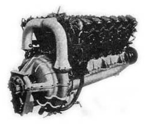
“Jumo 207B”
-The supercharger, a generous one, is powered by mechanical transmission. The engine gave 1,000 CV at sea level. The design began in 1939. They are engines for high altitude, being able to reach 10,000 meters (32,808 ft). They could be geared, in general from 0.602 to 1.
“Jumo 207A”
-They used to have an intercooler for air cooling due to the large compressor or double compressor as the case may be. The 207A-1 gave 880 CV and the 207A-3V, increased its power to 950 CV. Each cylinder had 4 injectors and the fuel pump was Bosch.
-In 1941, the 208, A and B versions, larger than the 207 came out. In a way it was a continuation of the 206. Only a dozen engines that were used in tests were made, and they remained like that, without going into production.
-The 209 was a derivative of the last mentioned engines but no more information is available.
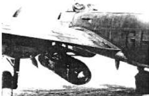
-Some of the giant Junkers G-38 plane, huge for the time, were powered by the mentioned Jumo Diesel engines. As they were mounted inside the wing some extensions were used.
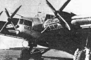
“Junkers G-38”
-Another curiosity was that between the fuselage and the first engine on the wing, at the leading edge, there were windows that allowed to look out of it and see the progress of the plane.
“Jumo engine for the G-38”
-For the same reason, it was easy to access the engines for a possible service while the plane was flying.
-Below we show an illustration of the Jumo 207-D six-cylinder with double piston in each of them. It is a 2-stroke engine that gave 1,200 CV at 3,000 rpm. Its weight was 1,430 pounds.
-We can see a large turbosupercharger at the rear, without it the power is 750 CV but without the ability to maintain it on high altitudes.
“Junkers Jumo 207-D” (At the NASM)
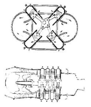
-In the case of the Junkers Jumo with opposed pistons within the same vertical cylinder, there were two basic Junkers systems.
-The best known is the one with the front gears to synchronize the two crankshafts and in one of them the output for the propeller.
-The other one has a single crankshaft and long connecting rods that connected to it from the opposite piston, as we see below.
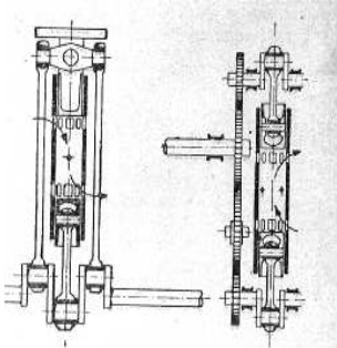
“Two Junkers systems”
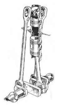
"Long-connecting-rod system in detail”
-The latter was done by Peugeot under license (see).
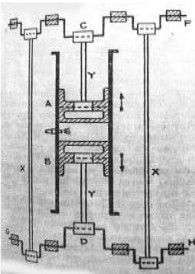
-But what continued common in both connecting rod systems, was the cylinder and the two opposed pistons with the injectors in the center, the inlet port on one side and the exhaust port on the opposite side.
“Compression”
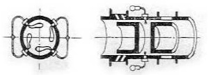
“Injection”
“Exhaust”
-Before continuing with the chronological order of the Jumo engines numbering, we will make a step back until 1921, since this line of diesel engines ended with 209.
-We recover the engines that ran on gasoline.
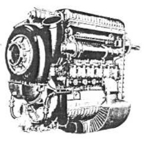
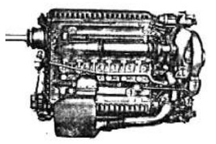
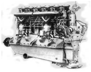
-The first one was the L.1, an engine with 6 upright cylinders inline that gave 80 CV to 100 CV, depending on the variant. They were air cooled and had a big fan.
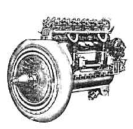
“Junkers L.1”
“Junkers L-1a”
-In the photograph above we see the L.1A engine from 1925 installed on an aircraft. We see the fan in the front part together with the propeller on the same shaft. It had a little more power because its pistons had 5 mm more diameter than those of the L.1.
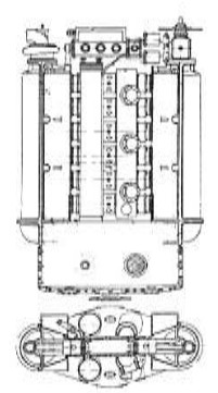
“Junkers L.2”
-The L.2 was based on the BMW IIIa, from which Junkers had obtained a license to develop it and went into production from 1924. It was the first engine used on the Junkers L-13 aircraft. The L.2a would reach 230 CV.
-The L.3 and L.4 were improvements of the L.2 obtaining the power with higher revolutions. But both projects were set aside in favor of the L.5. There were L.5 engines with one and two carburetors.
“L.5 with 1 and 2 carburetors”
-They were more developed, and gave 310 CV. Both were built from 1924/25. The L.5g gave 340 CV.
“L.5”
-From the L.5 there are other models such as -G, Ga and Z. The L.5 brought several records to Junkers.
-The L.15 was similar to the L.5 as we can see in the below illustration. It gave 280 to 310 CV
“L.15”
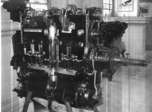
-The L.55 had the same cylinders as the L.5, but the engine had 12 cylinders in V and gave up to 650 CV.
-This engine was intended for the G-38 that we mentioned before. Later they would be replaced by the L.88 on that plane.
-The L.55 Type 1, 2 and 3 were made.
-There was the supercharged variant for high altitudes, as we see in the figure below.
“Otro L.55”
“L-55”
-The Junkers L-55 had a double mechanical compressor at the rear. It reached 625 CV at 1,520 rpm.
-The L-55 was a double L-5 in a 60° V with 12 cylinders. The same counts for the L-88, which is a double L-8.
-There is no information about an L.6, not even if it ever existed.
-The L.7 was a prototype developed from the L.2, of a sports style. This 4-stroke engine had six water-cooled cylinders.
“L.7, with one carburetor”
-There is another variant - or a confusion of the L.7 - with two carburetors and structural differences.
“L.7”
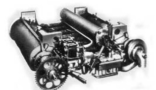
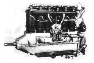
-The L-8 was an evolution of the L.2 and L.5 for larger aircraft. Some units were built around 1928, and they were installed on the G-38, but only the outer engines. It was the first Junkers engine with gearbox, as we see, with superimposed gears.
“L.8”
-It had six upright cylinders, and by 1929 it reached 420 CV.
- Derived from this engine was the L.88. It used the cylinder banks from the L.8, forming a V-12.
-The L.88 was from 1929 and gave 590 CV. The L.88a came out in 1932 with 800 CV.
-The L.88 replaced the L.55 on the G-38a aircraft.
“L.88”
-The L88a could achieve 800 CV at 1,850 rpm.
-L-88b version delivered 850 CV at 2,100 rpm. It was geared from 2’18 to 1.
“L.88 for the G.38a”
“L.88a”
“L.88a”
“L.88b”
“210 A / B”
-Now the gasoline “L” series has been treated, we continue with another series of gasoline engines that “breaks” with the previous Diesel Jumos.
-They are the Jumo 210, 211, etc., until 225.
-This new line of engines began in 1933 with the 210 and 211, 12-cylinder inverted V-engines.
“Junkers Jumo 210 C”
-The 210 are clearly identified by the ribs on both sides of the crankcase.
-In the first Me-109 aircraft, Jumo engines were used as well:
-210A giving 610 CV.
-210D giving 635 CV.
-210B giving 610 CV.
-210E giving 680 CV.
-210G giving 640 CV.
-210EG giving 640 CV.
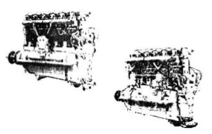
“Two Jumo 210”
-In the previous illustration we can see the differences of the cylinder heads and rocker covers between the 210G on the left and the 210S on the right.
-The 211 engines, similar to the 210, were designed by Neugebauer and Erfurth.
-They had an identical configuration of 12 cylinders in inverted-V at 60°. In fact it was made from the 210H design with greater displacement (35 liters). From this engine almost 70,000 units of various series were manufactured.
“Junkers 211”
“Jumo 211 at the MAE”
-The Junkers Jumo 211, in version A gave 950 CV at 2,200 rpm.
“211 F y J”
-The F and J versions were similar to the A in the general constitution, with a reinforced crankshaft, total shielding of the ignition system, DVL supercharger and its controls.
“211 F, rear view”
-With gearbox, the F and J engines could deliver up to 1,400 CV at 2,600 rpm.
-From the 211 there were the 211 A, B, C, D series etc. up to R.
-The 211 F with an auxiliary tank for the cooling glycol is shown below.
-Later we show a 211 D with bench included, giving an extraordinary feeling of a compact engine.
“211 F with auxiliary tank”
“211 D”
-The 211 N and P versions reached 1,500 CV, but the 211 were soon replaced by the 213.
“213 A”
-The 212 was a coupling of two 211 engines, totaling 24 cylinders that only remained an idea. However, it is considered a pre-development of the Jumo 222.
-The Jumo 213, like the shown A version, already used fuel injection with the pump placed between the V of the cylinders. They had a DVL supercharger.
-The ignition system was Bosch and the engine gave 1,750 CV at 3,250 rpm, so it was geared from 0’417 to 1.
-The Jumo 213 A.1 of the year 1943, was seen on the Focke-Wulf 190D and Junkers Ju-88G6, in addition to the Ju-188. With the same power as the previous 211 A.
-They had water-methanol injection so that for a while the power could increase to 2,100 CV.
“213 A.1”
-In this first photograph we see the coupling of the propeller by grooved shaft and thereafter it is presented with the typical German platina for the propeller coupling.
“Jumo 213, with platina”
“Jumo 213 document”
-There was the 213C, which allowed a cannon to fire through the propeller shaft.
-The E gave 1,750 CV, the F gave up to 2,060 CV, the J gave 2,600 CV and the S gave 2,400 CV, and up to 8,000 feet of altitude. The Jumo 213 T with turbocharger gave 1,750 CV at sea level, 1,760 CV at 1,650 feet and still 1,600 CV at 38,000 feet thanks to turbocharging.
“Junkers 213”
-In the engine reserve of the Paris Air Museum is a Junkers 213 model engine, although in an inverted position, in this case with the V upright.
“Junkers 213”
-At first glance it is difficult to identify that it is 213 because the aspect varies completely from this perspective.
“Another view of Jumo 213, with some inclination”
-It is not a whim that it has the bow up. To fully fit, the photographer already had his back on the wall.
-It continues in the upright V position instead of the normal inverted V position.
It seems that the Jumo 214 to 221 denominations were reserved to be occupied by future developments of the Jumo 204 to 211 engines, but this is not certain.
-Anyway there are no new engines identified as such. Only the Jumo 218 seems to be a double 208, without further continuity.
“Jumo 222”
-The 222 was the next solution to obtain greater powers. It was water cooled and had 24 cylinders in 6 rows of 4 cylinders.
“Jumo 222”
-Two rear views have been offered. Let's say it's a "hexagonal" engine. The -A and -B (1st series) delivered 2,500 CV at 3,200 rpm.
-It had an important gearbox, because in the A series the propeller turned to the left, and in the B version it turned to the right.
“Gearbox detail”
-From 1939 to 1944, series from letter A to H were made.
-Precisely the G and H had turbocharger instead of simple supercharger and intercooler.
“Almost frontal view of 222”
-The 222 with 24 cylinders offered great power, but was never fully developed.
-Now we have located another photograph of the 222 without the bulky gearbox.
-It is about the -A and -B.
-We also see that the hoods, or engine fairing, are more similar to those of a radial engine, but on the front there are radiators.
“Jumo 222, -A or -B”
“222 fairing”
-We see that the propeller did not have the classic cone but that in its central part it had the cooling-air intake for the radiators (water and oil) and before reaching the engine, the typical blinds to control the temperatures.
“Jumo 223, front view”
-The 223 (and 224) are of a different formula than the previous 222 engine.
-They are four Jumo 207 engines joined by their extreme crankshafts, located externally and tangentially as well as the engine devised by Ing. Causan.
-The combustion chambers were common.
“Causan's design”
-They used four Jumo 207 six-cylinder engines, so the total number of cylinders was 24.
-But there were 4 crankshafts less in this operation since each engine takes advantage of the next engine.
“Jumo 223 real look”
-It is said that the 223 was in some way predecessor of the Napier Deltic, triangular with three engines.
“Jumo 223 side view”
-The displacement was 29 liters in total and the calculated power of 2,500 CV was given at 20,000 feet. Naturally, it was supercharged for being a two-stroke engine to exercise that power at high altitudes.
-It weighed 2,300 Kg and had a diameter of 130 cm. approximately.
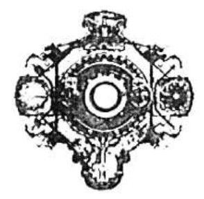
“Jumo 223 front look”
-The 223 engine was abandoned in favor of the 224, similar to the 223 in design, using four 207B-3 engines with a theoretical power of 4,.500 CV. These engines were developed at the Junkers plant in Dessau.
-The 224 did not operate nor did it go into mass production. Only static tests are known.
-The Jumo 225 with 36 cylinders and 70 liters of total displacement was a further development of the Jumo 222 G/H for 4,000 to 5,000 CV. It was the last engine in the Jumo piston series.
-But if this seems to be the end of the piston-engine development of the Junkers brand, there are still other projects possibly based on 222, 223 or 224 type engines. Or other planned X-engines.
-It is a motorjet whose project we show below.
“Junkers motorjet”
-That is, a compound motor, acting as a jet, has a piston engine inside to drive the compressor, in the style of the CC.1 and CC.2 from Italian Caproniampini.
-And to finish this chapter of piston engines, a reminder of the French Arsenal engine, which used cylinder blocks from the 212 and 213 engines that were requisitioned after the war. They built a massive 24-cylinder, 4,000 CV engine as the illustration below reminds us. They were blocks that were recovered at the end of WWII and taken to France in 1945/46.
“Arsenal-Junkers”
-As for the construction of turbojet engines, Junkers together with BMW were commissioned to develop Class I engines, of greater power (relative, of course). Heinkel made them in the lower category, but a HeS-3b engine and a Heinkel He-178 aircraft were the first jet aircraft to fly, in August 1939.
-In 1936, Magdeburger Werkzeugmaschinenfabrik already started work on the jet that was going to be the Jumo 109-004. In 1939, Otto-Mader took over the construction and from there it went to Junkers.
-And it is in 1939 that Junkers begins to work on it, with engineers Mueller and Wagner, directed by Professor Anselm Franz, an Austrian engineer.
“Magdeburger project”
“Jumo 109-004”
-It is said that the first engine was a derivative of the T-1 (old project), but what seems certain is that the Jumo 109-004A, was built from scratch.
-It ran in October and flew on a Me-110 in 1941. It delivered almost 600 Kgf of thrust at 900 km/hr. The engine had an 8-stage axial compressor, 6 cannular combustion chambers and a single turbine. The nozzle was adjustable to keep the values as constant as possible in the different maneuvers.
“Jumo 109-004 on the Me-110”
-On land and below 50% power the nozzle bulb was inwards and up, between 50% and 90% it was outward.
-For the turbine there was assistance from AEG, who had experience in generating electricity with steam turbines.
-Also there was a curious anecdote in which a technician used a musical tuning fork to calculate the length of the blades and eliminate vibrations and breakages.
“Jumo 109-004 cutaway”
-In 1941 Junkers made the test series, such as 004V.
“Jumo 109-004V nacelle”
- Jumo 109-004A-O is from 1942.
“Jumo 109-004A-O nacelle”
-And the 004B-1 nacelle from 1943.
“Jumo 109-004B-1 nacelle”
-Some 30 turbines were manufactured. It gave way to the A-O and both turbines were considered a preproduction accumulating experience with them, even in flight, until reaching the 109-004B.
-First appeared the B-0 (January 1943) and later the B-1 model that was already built in greater quantity from 1944.
“Jumo 109-004B1”
-There were variants such as B1, B2, B3 and B4. Also the C with 1,000 Kgf from the year 1944. The variant D, with 930 Kgf, was from the same year.
“109-004B-1 cross-section”
-The E gave 1,200 Kgf of thrust in 1945, the same as the F. The G gave 1,700 Kgf of thrust and the H reached 1,800 Kgf.
-The 109-004D reached the mentioned 930 Kgf on a bench, and flew at the beginning of 1944 on the Me-262, to which it was destined, together with the Plow 234. With an afterburner test it gave 1,200 Kgf.
-In fact, the 109-004A was the first development as we have told, but the truly operational ones were the B1 to B4 versions.
-We note that the jets are also known as Jumo, naturally it is a contraction of JUnkers MOtoren.
-The -004C was a B with auxiliary fuel injection (afterburner). The -004D4 had improvements in fuel regulation and the -004E was similar to D4 with a shorter nozzle.
They built between 5,000 and 6,000 units of all these engines in a very short time, although there were no more than 250 operational aircraft.
-Someone tried to take the plans to Japan but it seems that like the BMW plans they suffered mishaps on the submarines that carried them. In the case of Junkers, it seems that these plans never arrived. It was intended to enhance the Nakajima J8N1.
-However, the Russians were lucky with German and Austrian material, documentation and technicians with whom to build their first engine, the RD-10, then under the direction of N.D. Kuznetsov. These engines were intended for the Yak-9 and -15. Of course, they were based on the 109-004.
“RD-10”
-RD means "Reactivny Dvigatel". Reaction engine.
-The next engine that was being developed at Junkers, in the middle of the war, was the 109-012, of Class-I but due to the poor results, it started being Class II.
“Jumo 109-012”
-It was planned for a thrust of 2,780 Kgf. The 109-012 was an engine that was planned for the fast Ju-287 bomber.
-It had a 11-stage compressor and 2-stage turbine. At the time of the end of the war it had not yet been tested in flight.
-Finally the 012A became a Class III. It was designed in the spring of 1944.
“Jumo 109-012A”
-The next and logical development of -012 was a turboprop, basically the same engine with gearbox and contra-rotating propellers. It was the 09-022.
-Also in Russia (USSR then), from the -012 and -022 engines they developed the NK-012 turboprop, with Ferdinand Brandner, an Austrian engineer.
“Jumo 109-022”
-The Jumo 109-004B1 was manufactured in Czechoslovakia by Letecke, as M-04.
-There are two photographs of the Junkers Factory Museum, which we would like to insert here as it was destroyed in the WWII by the Allied bombings.
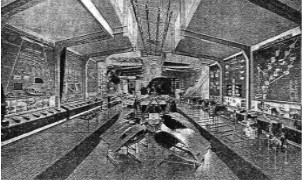
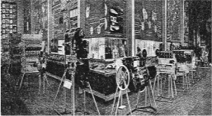
“Junkers Museum in 1942”
-Later there is a current Junkers Museum, but without masterpieces as there were at that time.
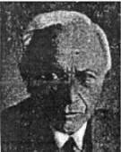
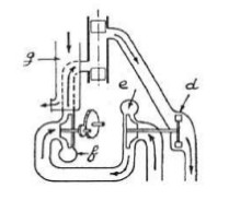
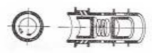
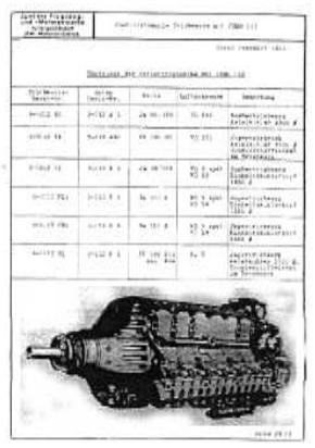
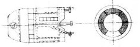
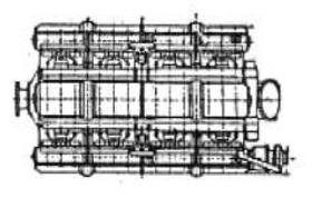
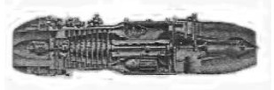
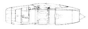
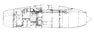
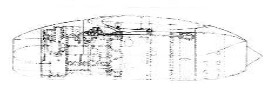
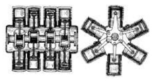
From Appendix 6: When the Fo.2 was presented as a new engine, this was atypically done with a schematic drawing and a cylinder block in the Popular Mechanics magazine.
-Its position was horizontal to be installed between chassis or on the wings. The truth is that when they became reliable and useful, series 205, 207 etc, they worked in an upright position and were used exclusively in aviation. They were two-stroke diesel engines.
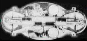
“Junkers Fo.2 architecture”
“Bare cylinders”
-It has two crankshafts, one at each end, in their crankcases and joined by the cylinders.
-The cylinders have the intake ports on one side and the exhaust ports on the other. The combustion chamber is created in the center when the two pistons are at their BDC.
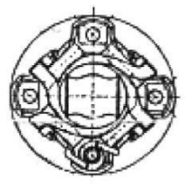
-By the main text we know that there are two types of connections between connecting-rods and crankshafts to achieve a unique output for the propeller.
“Curious assembly of long and short cranks”
-This system was used by Peugeot and Gobrón-Brillié itself, however almost all Junkers engines linked the two crankshafts with a gear train.
-For the great G-38 aircraft there were two main assemblies.
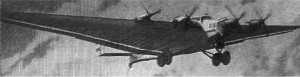
“Junkers G-38, four-engined aircraft”
-The G-38 had windows for passengers at the leading edges of the wings. That big it was. There was the G-38 with the characteristic opposed piston engines.
“Junkers Jumo engine for the G-38”
-For the G-38a, the Junkers L.88 engine was already used like the one we see below with an extension.
“Junkers L.88 engine”
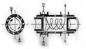
-From the "NACA Technical Memorandum No. 706" report, we have the illustration of the linear drawing of the Jumo 4, an opposed-piston Diesel engine that is inserted below for being very clear and didactic.
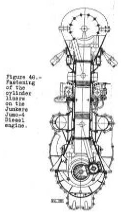
“Junkers Jumo 4”
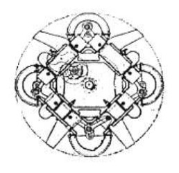
From Appendix 7: We now have a beautiful figure showing the moving parts of the opposed-piston Junkers engine.
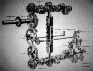
“Schematic drawing or the mechanism, two-stroke Diesel”
From Appendix 9: Well-known brand of aircraft and engine manufacturers. Especially the engines for their own airplanes.
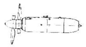
-But a curiosity has been found, a Jumo that is not aviation. We mention it here because it will surely get the reader's attention.
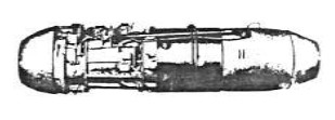
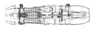
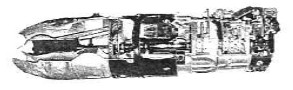
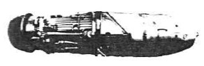
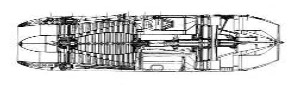
-It is an engine for a torpedo, with aeronautical technique.
-What stands out, is that instead of having normal valves, it has one disc valve per cylinder.
-This has been seen in a Daimler Benz, the DB-612.
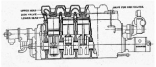
“Side view of the engine”
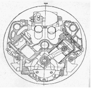
“Frontal cross-section”
-The single-carburetor Junkers L.5G engine can be seen at the Vienna Transport Museum in Austria.
“L. 5G engine, in photo by Evzen Vsetecka, from AEHS”
"On the right side it is more sectioned"
-What attracts attention again - as in the case of Hiero, from this same museum - the detail that the pistons have grooves (4) and holes to put oil on the contact surfaces. But some pistons are mounted upside down. Careless detail
-At the Hugo Junkers Technical Museum in Dessau, there is a Jumo turbojet (JUnkers MOtoren) model 004. Complete to admire in detail.
-One of these details is that the starter ring -the cable- appears through a side hole of the cone (at 2 o'clock), instead from the front through which the cooling air for the Riedel starter engine flows in.
“Junkers Jumo 004”
-There is also a Jumo 213, at the Dresden Military Historical Museum. The type of cutaways and visibility of internal parts is interesting.
“Jumo 213” (E.V.)
-The author was very interested in the front end of the crankshaft that appears through the removed front cover and the reduction gear of significant size, just below it.
From Appendix 10: New photograph of the rear of an L5
"Fan shell, possibly from L-1a"
"Drawing of a Junkers patent"
-The schematic drawing of the six-row, four-cylinder engine can clearly be that of the Jumo 222 with twenty-four cylinders in total.
-It is the “Viertakt-Reihenster Motor. Patent 711137 ”
Engines of JUNKERS
Model: Fo.1
Arquitecture: Single-cylinder
Cooling:
Total Displacement:
Bore / Stroke:
Power:
Weight:
Model: Fo.2
Arquitecture: 2-stroke6-cylinder Opposed piston engine
Cooling:
Total Displacement: 17.1 Ltr.
Bore / Stroke:
Power: 500 CV @ 1800 rpm
Weight: 776 Kg
"Fo.2, rear view"
Model: Fo.3
Arquitecture: 5-cylinder Opposed piston engine
Cooling:
Total Displacement:
Bore / Stroke:
Power: 850 CV
Weight:
"Junkers Fo.3, rear view"
Model: Fo.4
Arquitecture: 6-cylinder Opposed piston engine
Cooling:
Total Displacement: 28.5 Ltr.
Bore / Stroke:
Power: 750 CV @ 1600 rpm
Weight: 800 Kg
"Junkers Fo.4"
Model: Jumo 109-004
Arquitecture: Turbojet
Compressor/s: 8-stage axial compressor
Combustion chambers: 6 cannular combustion chambers
Turbines: Single-stage turbine
Power / Thrust: --- / 600 Kgf
Weight:
"Junkers 109-004"
Model: Jumo 109-006 (ver Heinkel tambien)
Arquitecture:
Compressor/s:
Combustion chambers:
Turbines:
Power / Thrust: / ---
Weight:
Model: Jumo 109-012
Arquitecture:
Compressor/s:
Combustion chambers:
Turbines:
Power / Thrust: / ---
Weight:
"Junkers 109-012"
Model: Jumo 109-022
Arquitecture:
Compressor/s:
Combustion chambers:
Turbines:
Power / Thrust: / ---
Weight:
"Jumo 109-022"
Model: Jumo 204
Arquitecture: 6-cylinder Opposed piston engine
Cooling:
Total Displacement: 28.6 Ltr.
Bore / Stroke:
Power: 740 CV @ 1800 rpm
Weight: 750 Kg
"Jumo 204"
Model: Jumo 205
Arquitecture: 6-cylinder Opposed piston engine
Cooling:
Total Displacement: 16.6 Ltr.
Bore / Stroke:
Power:
Weight:
Powers up to 650 CV in the D version
"Jumo 205C"
Model: Jumo 206
Arquitecture: 6-cylinder Opposed piston engine
Cooling:
Total Displacement: 35 Ltr.
Bore / Stroke:
Power: 1000 CV
Weight:
Model: Jumo 207
Arquitecture: 6-cylinder Opposed piston engine
Cooling:
Total Displacement:
Bore / Stroke:
Power: CV
Weight:
Power up to 1,200 CV at 3,000 rpm in the 207D version.
"Jumo 207B"
Model: Jumo 208
Arquitecture: 6-cylinder Opposed piston engine
Cooling:
Total Displacement: 25.5 Ltr.
Bore / Stroke:
Power: 1340 CV @ 2800 rpm
Weight:
Model: Jumo 209
Arquitecture: 6-cylinder Opposed piston engine
Cooling: Liquid
Total Displacement: 16.2 Ltr.
Bore / Stroke:
Power: 1210 CV
Weight:
Model: Jumo 210
Arquitecture: 4-stroke12-cylinder Inverted V-engine
Cooling: Liquid
Total Displacement: 19700 cc
Bore / Stroke: 124 x 136 mm
Power: 610 CV @ 2700 rpm
Weight:
-210A giving 610 CV.
-210D giving 635 CV.
-210B giving 610 CV.
-210E giving 680 CV.
-210G giving 640 CV.
-210EG giving 640 CV.
"Junkers Jumo 210 C"
Model: Jumo 211
Arquitecture: 4-stroke12-cylinder Inverted V-engine
Cooling: Liquid
Total Displacement: 35000 cc
Bore / Stroke: 150 x 165 mm
Power:
Weight:
211A with 950 CV a 2200 rpm.
211F y 211J with 1400 CV a 2600 rpm. con reductora
211 N y P with 1500 CV
"Junkers Jumo 211"
Model: Jumo 212
Arquitecture: 24-cylinder
Cooling:
Total Displacement:
Bore / Stroke:
Power:
Weight:
The 212 was a coupling of two 211 engines
Model: Jumo 213
Arquitecture: 4-stroke12-cylinder Inverted V-engine
Cooling:
Total Displacement: 35000 cc
Bore / Stroke: 150 x 165 mm
Power: 1750 CV @ 3250 rpm
Weight:
213A with 1750 CV at 3250 rpm
213E with 1750 CV,
213F with 2060 CV
213J with 2600 CV
213S with 2400 CV
213T with 1750 CV
"Jumo 213 front view"
Model: Jumo 222 A/B
Arquitecture: 4-stroke24-cylinder Radial
Cooling: Liquid
Total Displacement: 46500 cc
Bore / Stroke: 135 x 135
Power: 2460 CV @ 3000 rpm
Weight: 1170 Kg
"Jumo 222, angled front view"
Model: Jumo 222 C/D
Arquitecture: 4-stroke24-cylinder Radial
Cooling: Liquid
Total Displacement: 49900 cc
Bore / Stroke: 145 x 140
Power: 2960 CV @ 3200 rpm
Weight:
Model: jumo 222 E/F
Arquitecture: 4-stroke24-cylinder Radial
Cooling: Liquid
Total Displacement: 49900 cc
Bore / Stroke: 140 x 135 mm
Power: 1930 CV @ 3000 rpm
Weight:
Model: Jumo 222 G/H
Arquitecture: 4-stroke24-cylinder Radial
Cooling: Liquid
Total Displacement: 46500 cc
Bore / Stroke: 135 x 135 mm
Power:
Weight:
Model: Jumo 223
Arquitecture: 2-stroke24-cylinder Opposed piston engine
Cooling:
Total Displacement: 29 Ltr.
Bore / Stroke:
Power:
Weight: 2300 Kg
"Jumo 223"
Model: Jumo 224
Arquitecture: 2-stroke24-cylinder
Cooling:
Total Displacement: 68 Ltr.
Bore / Stroke:
Power: 4500 CV @ 3000 rpm
Weight: 2600 Kg
Model: Jumo 225
Arquitecture: 36-cylinder
Cooling:
Total Displacement: 70 Ltr.
Bore / Stroke:
Power: 4000 CV
Weight:
Model: Jumo 4
Arquitecture: 6-cylinder Opposed piston engine
Cooling:
Total Displacement:
Bore / Stroke:
Power: 710 CV @ 1800 rpm
Weight:
"Jumo 4, cutaway"
Model: Jumo 5 (a veces V)
Arquitecture: 6-cylinder Opposed piston engine
Cooling: Liquid
Total Displacement: 16.6 Ltr.
Bore / Stroke:
Power: 405 CV @ 2100 rpm
Weight: 510 Kg
"Jumo 5"
Model: L-1
Arquitecture: 4-stroke6-cylinder In-line
Cooling: Air
Total Displacement:
Bore / Stroke:
Power: 80 CV @ 1800 rpm
Weight:
"Junkers L.1"
Model: L-15
Arquitecture: 4-stroke6-cylinder In-line
Cooling:
Total Displacement:
Bore / Stroke:
Power: 310 CV
Weight:
The L.15 was similar to the L.5.
"L.15"
Model: L-2
Arquitecture: 4-stroke6-cylinder In-line
Cooling: Liquid
Total Displacement: 19100 cc
Bore / Stroke: 150 x 180 mm
Power: 230 CV @ 1550 rpm
Weight: 290 Kg
"Junkers L.2"
Model: L-3
Arquitecture: 4-stroke6-cylinder In-line
Cooling: Liquid
Total Displacement:
Bore / Stroke:
Power:
Weight:
Improvement of the L.1
Model: L-4
Arquitecture: 4-stroke6-cylinder In-line
Cooling: Liquid
Total Displacement:
Bore / Stroke:
Power:
Weight:
Improvement of the L.2
Model: L-5,
Arquitecture: 4-stroke6-cylinder In-line
Cooling: Liquid
Total Displacement: 22900 cc
Bore / Stroke: 160 x 190 mm
Power: 310 CV @ 1500 rpm
Weight: 315 Kg
"Junkers L.5"
Model: L-7
Arquitecture: 4-stroke6-cylinder In-line
Cooling: Liquid
Total Displacement: 4200 cc
Bore / Stroke: 90 x 110 mm
Power: 108 CV @ 2200 rpm
Weight: 120 Kg
"Junkers L.7 with two carburetors"
Model: L-8
Arquitecture: 4-stroke6-cylinder In-line
Cooling: Liquid
Total Displacement: 22900 cc
Bore / Stroke: 160 x 190 mm
Power: 420 CV @ 2100 rpm
Weight: 420 Kg
"Junkers L.8"
Model: L.55
Arquitecture: 4-stroke12-cylinder V-Engine
Cooling: Liquid
Total Displacement: 45800 cc
Bore / Stroke: 160 x 190 mm
Power: 625 CV @ 1520 rpm
Weight: 575 Kg
"Junkers L.55, rear view"
Model: L88
Arquitecture: 4-stroke12-cylinder V-Engine
Cooling: Liquid
Total Displacement: 45800 cc
Bore / Stroke: 160 x 150 mm
Power: 590 CV @ 1870 rpm
Weight: 794 Kg
"Junkers L.88a"
Model: Motojet cyl. in X
Power: @ rpm Other details: