

Updated: 02-Jan-2020
(Allison continued from part 1)
-Possibly the one below is a version of this engine or a variant.
"Similar engine but turboprop"
-As discussed in the main text, Allison has made a lot of trials with heat recoverers. Perhaps the most published was the T-78.
"T-78 in a nice illustration"
-With the T-78 they tested two types of heat exchangers, the circular and the longitudinal, depending on the direction of the cells.
"Circular and longitudinal honeycombs in the T-78"
-Now we show an experiment that is fairly exaggerated in size of exchanger body. It is short and has a large diameter compared with the highly stylized T-78.
-In the illustrations below we see these details and the airflow from the compressor outlet to the exchanger and back to the combustion chambers.
"Allison experimental"
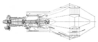
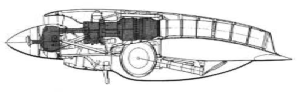
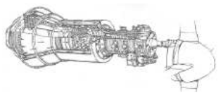
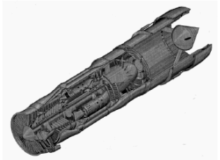
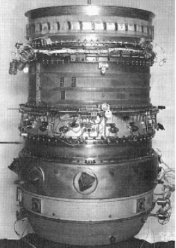
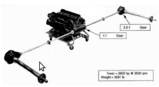
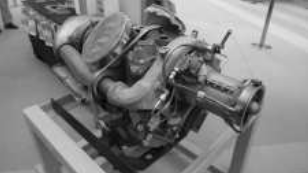
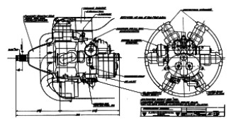
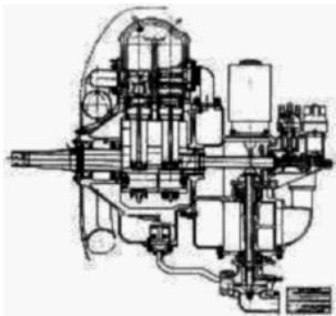
-Continuing with the scrutiny caused by this new Allison chapter and with the information obtained from the 2009 AEHS Convention, we show you the T-61 engine that has dual shaft, HP and LP.
“T-61 cutaway with twin shaft”
-The LT rear turbine drives the front LC compressor and at the same time the transmission to the propeller.
-The first HT turbine stages drive the second HC compressor.
-As is typical in American turboprops, the gearbox can be reversed and moved up or down to suit aircraft design.
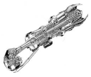
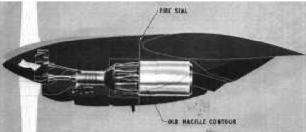
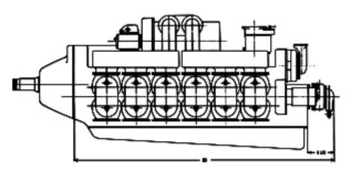
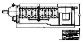
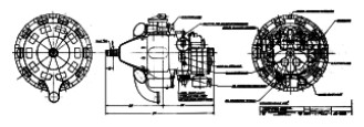
-If in the T-61 cutaway drawing we see the gearbox on the lower side, in the following figure it is on the upper side.
"T61 with upper gearbox"
“Allison T61 mounting diagram”
-This possible combination allows installing engines without cutting the wing structures for attachment.
-We see in the T-78 illustrations that they also were planned to have a versatile gearbox position, upper or lower. The wing structure remains entire with the exhaust air flowing above or below it.
"Allison T78 with upper gearbox"
-In this assembly the engine is under the wing, possibly high-wing aircraft's, with the compressor air intake below the propeller.
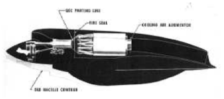
"Allison T78 with upper gearbox"
-Possibly a low-wing aircraft, the air intake is above the propeller to minimize FOD ingestion.
-And as a final touch, an Allison design from 1963 similar to the Rolls-Royce RB.202 engine (see).
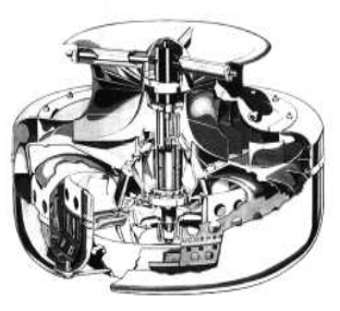
"Allison Model 615, lift engine"
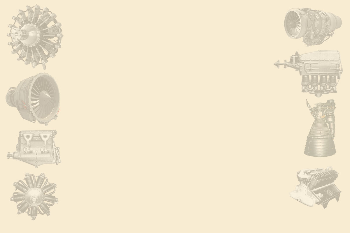
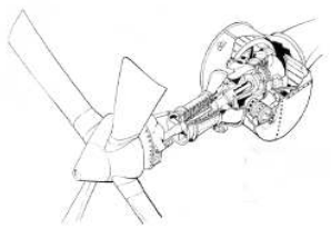
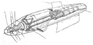
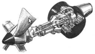
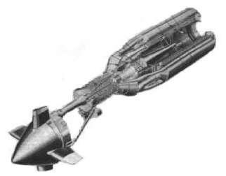
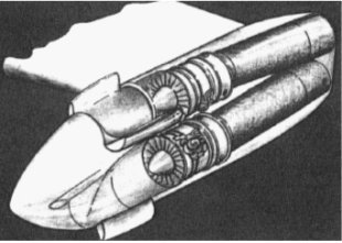
-In the period of cruise missile design proliferation, Allison provided a small turbine engine driving two multiple retractable, contra-rotating, propellers.
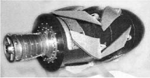
"Allison Prop-fan for cruise missiles"
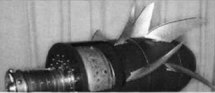
"Allison prop-fan with the propeller blades unfolded"
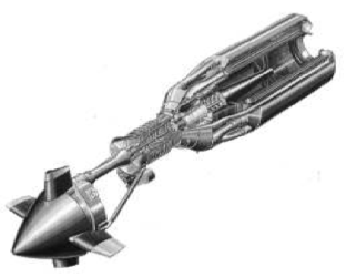
This axial compressor clearly is from an Allison 250. They could be installed in different versions such as vertical launch, drop in the air and by a torpedo tube.
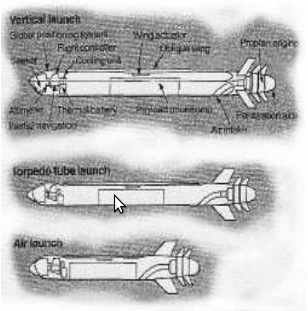
"Three proposed systems for this engine"
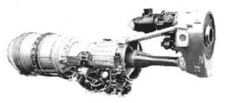
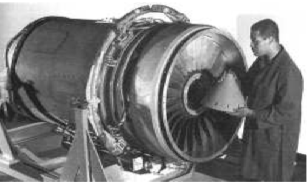
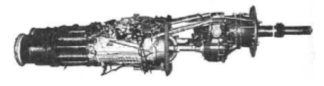
-Now, from an advertisement in the 1990's: the Allison GMA-2100 engine was certified in April 1993. Just as it is on the transportation bed.
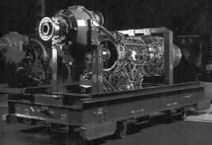
"Allison GMA2100"
-It was the time when Allison still belonged to General Motors, as we see in the following logo. Shortly after that it would be taken over by Rolls-Royce.

"Allison logo when it was still with GM"
-In the main text it was mentioned that the AE-3007 was based on the T-406 without illustration. Now we have one.
"Allison T-406"
-Below we insert better pictures of these engines.
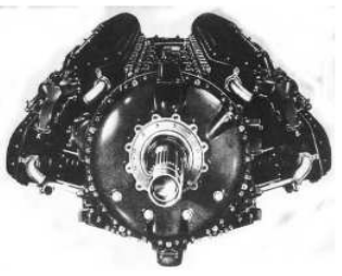
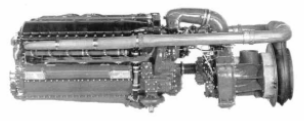
"The Allison V-3400, A double V-1700"
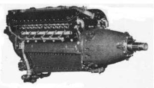
-We continue with various V-1700 views from advertisings at the end of WWII.
"Different Allison V-1700 views"
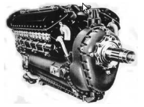
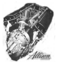
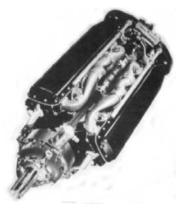
-Now again the American fighter P-40's engine, the Allison V-1710 with elongated nose cone for aircraft design requirements.
"Allison V-1710"
-To show the cone from the inside and that it actually is hollow, there is the illustration below.
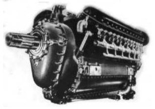
-Perhaps the most interesting is the reduction gear that, because of the crankshaft being nearly in alignment with the extended propeller shaft, is not of any conventional type.
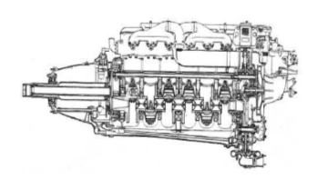
"Detailed diagram of the gear"
-Continuing with the reduction gear, the propeller shaft has a drum at its end with gear inside and that is where the gear wheel at the end of the crankshaft drives the propeller gear. Again, this is not common.
The T-40's double installation is shown below in the following two illustrations.
“Photo and drawing of the T-40 double Allison” (PiP)
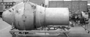
-The T-78 engine has always been considered interesting because it tried to recover some of the heat lost through the exhaust. The T-78 was the 525 in the Allison nomenclature. (B-2, etc.).
"Allison T-78 -scale model-"
-In the cylinder at the rear is a heat exchanger, there were ceramic ones.
"Allison T-78 diagram"
-The hot exhaust gases passed through a rotary drum which retained heat and yielded it again before entering the air into the chambers. So it recovered the heat.
-This rotary drum was designed to rotate in transverse position. This was a Chrysler system as well. (Show).
"Previous tryout of the T-78"
"Final aspect of the scale model"
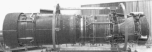
To obtain the T-40 turboprop, Allison coupled two T-38s (Model 501).
"Allison T-40"
-This twin power plant was installed in several seaplanes like the Convair P5Y and R3Y. It was also installed in other brands such as Lockheed, North American or Douglas.
-But perhaps it was a spectacular application when, as the Allison T-56 not being available yet, it was mounted in the XF-84H prototype.
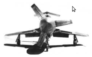
"The Republic XF-84H"
-When this trimmed propeller reached 3000 rpm it entered the supersonic area losing its effectiveness. Generally it made an exaggerated noise and generated frequencies that created health problems for flight and ground personnel, so it was known as the "Thunderscreech".
-Interestingly, in the US there were brands specialized in radial engines such as Pratt & Whitney and Wright and in liquid-cooled engines like Allison and Packard.
-Because of equipment or need according to the aircraft designers they bet for one system or the other. The advantages of both systems are different. We now have a diagram that shows the frontal areas -for the same power- where we can see that it is clearly smaller for the water-cooled V12s.
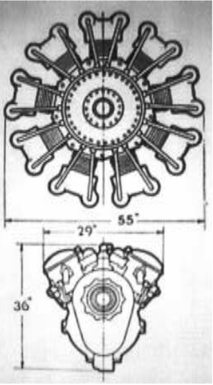
"Comparing both types"
-A typical Allison installation was the Bell Airacobra, which appears completely in the main text but it does not appear installed together with the pilot's position as seen in this diagram below.
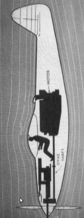
“The Bell Airacobra is only a platform to carry a
Powerful 1.5-inch cannon, and guns”
-Due to the cannon, the engine and gearbox layouts are according to it.
-There are appearing other models that are not mentioned in the main text, perhaps for not having passed the experimental status and not having entered in production and therefore did not become general knowledge. However, we confirm.
They are the 503, 504, 545, 89, 102, T-39, T-44, T-54, T-61, T-80. We are looking for illustrations.
From appendix 7: On a visit to the museum in Munich the engines are presented as from the "Allison Division of General Motors" as it was in the beginning.
-We know that later it became "Detroit Diesel Allison"
"Allison 250-C18"
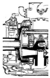
-The engine is open, so we can see the two turbines that drive the compressor and the two "power" ones.
-The front chamber is single and in front of it we see the compressor discharge valve. It is a turboshaft.
-The origin of Detroit Diesel Allison on the information panel has been corrected.
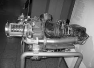
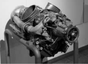
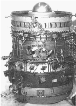
-The next Allison engine is the J-33 mounted in Lockheeds F-80 and T-33 (F-80's two-seater version). This one does come from the genuine Allison in Indianapolis.
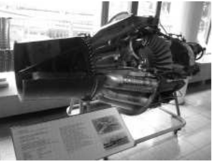
“The J-33 A-35 in Munich” (photo JG)
-The engine is cut out for education, emphasizing the double-sided compressor.
-From the author's (Ricardo Miguel) training period in the military we show two study "cribs".
-One represents the fuel system and the other the starter system.
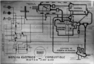
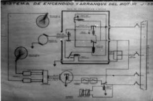
“Allison J-33 A-35 systems”
-From appendix 9: We are continuing to expand each brand with new appearances.
-We have a photograph of the J35 in its standard version and with afterburner.
"Allison J-35 with and without afterburner"
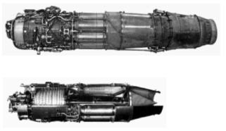
-In this Allison addendum we bring some of the engines designed by GE that had to be manufactured by Allison in the 1950's, depending on the capabilities of each factory.
"Cutaway drawing J-89"
“XJ-89”
-Actually it was called XJ-89 in its experimental phase. It is a low-bypass-Turbofan.
-It has a variable area plug nozzle, giving a variable output by means of an outer annular duct and the inner cone.
-It delivers 34500 lbs of thrust with afterburner. They worked on this prototype from 1956 to 1959.
-The Allison XJ-99 were called "Lifters", and were placed vertically inside aircraft fuselages. They were designed between 1968 and 1971.
-Two XJ-99 versions were made, the short one and the long one.
-Both with annular combustion chambers, although for the short one is mentioned that the gas flow is toroidal.
“The XJ-99 Short Lifter"
“The XJ-99 Long Lifter"
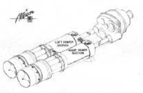
-These engines were intended for applications such as the American FRG/VTOL fighter or as takeoff aid in the KC-135s. They were twin assembled and horizontally mounted at the ends of the wings.
"Project for the KC-135"
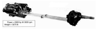
-The V-1710 series was widely used in WWII and multiple versions were made.
-Based on an engine like we see in the main text in the V-1710-E version, with a power drive on the front and on the rear. Here the gear and PTO (Power Take Off) are coupled with extensions up to the gearbox, that is located more to the bow of the aircraft.
"Compound version"
-At the rear drive, mechanical driven superchargers can be mounted, apart of the turbocharger that can be driven as well.
-In the case of "Compound" engines, the exhaust gas is driving a turbine recovering mechanical energy on the crankshaft. See the picture above.
“V-3420 powering a contra-rotating propeller”
-In the double-V-1710, which is the V-3420 like the one in the illustration above, the gear housing that couples the two power plants has individual transmission shafts towards the second gearbox at the plane's nose.
-In this case it is used for contra-rotating propellers.
“V-3420 powering counter-rotating propellers”
-Or as in the case of the above diagram, the output is bifurcated to a "false twin".
-The Allison 250 C-18A for military activity has a different nomenclature, it is the CT-63-M5A.
-At least it is seen in the main museum of Japan.
-It delivers 317 hp at 35,000 rpm.
"Allison CT-63-M5A"
From Appendix 10: Assigned to the Allison brand, they made some special engines from the 1920s until the mid-1940s. It was an unusual design as the cylinders were in pairs, and using a common combustion chamber with a 2-stroke cycle.
-They were actually designed at the General Motors Research Laboratory: the GMRL.
-The first designs would be a 10 and 12-cylinder boxer, although we have only a design of the 12-cylinder with 24 pistons. (12 pairs in a common chamber).
By 1932 Allison made a double twelve-cylinder engine, with U cameras, and two strokes. It was a horizontally-opposed, 12-cylinder engine.
"Allison 12C25"
-From the same year is the radial engine known as U-749.
"Motor Allison U-749"
-And another larger one known as U-1240.
"Allison U-1240"
-Allison radial models varied from 4 to 6 and 10 double cylinders (U-1240). See GMRL.
-From the use of these double cylinders radial engines came the U-173, U-744, U-1240 (U-1000 test engine), U-250, X-250, XR-250. Some of them are presented in the main text.
-The U-173 radial engine gave 90 hp only. It had four double cylinders with every pair connected with a common combustion chamber.
-As it was running with a two-stroke cycle, a blower or supercharger was needed to force the mixture into the first cylinder. Therefore they used a mechanical Roots.
"U-173"
"XR-250"
-New photo of the Liberty based Allison engine, with 12 cylinders in inverted V.
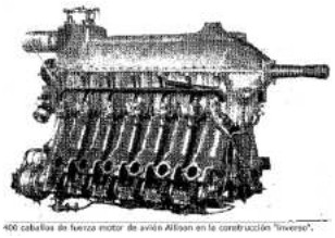
“Liberty based Allison inverted V-12 giving 400 hp”
Engines of ALLISON (2nd part)
We have no more detailed engine information for this brand. We continue our search. Any help will be appreciated.