

Updated: 18-Aug-2022
Mr. Rochefort presented an engine to the French Aeronauctics Technical Service.
-It did not pass the trials after two years of having started them.
-The operating principle was known since 1928, with six opposed cylinders, two-stroke, two crankshafts and air cooled.
-Diesel with low pressure power allowed it to work with various fuels, simply by changing faucets, such as gas-oil, lamp oil, gasoline, benzol, 90° industrial alcohol, etc. and without stopping the engine from running. Ideal for the French colonies.
-Le Service Technique de L'Aeronautique was interested in the Rochefort engine, as it used heavy oil without being a Diesel.
-They recommended the adaptation of another engine to which the cylinders had to be transformed to receive the spray injectors.
-The camshaft had to be adapted as well, it also had to have the cams for the injector-sprayer.
-It seems that it was a 4-stroke Lorraine engine.
-The principle seems to be that it had a pre-chamber where the mixture entered and at the end of compression cycle and with high temperature, a valve was opened that communicated the explosive mixture with the main cylinder.
“Insufficient interpretation of the Rochefort system”
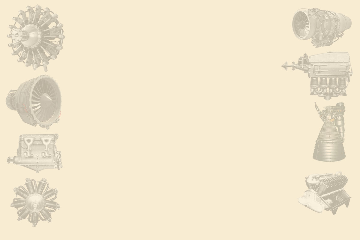
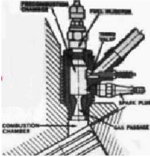
From Appendix 6: This special engine is already mentioned in the main text. It had a third valve better detailed in the below figure, (B).
“Rochefort schematic drawing”
-It seems that there were two versions. Rochefort's proposal included an interconnection duct (C) between cylinders that achieved a balance between them.
-In the first version, during the compression cycle, valve B remained open and in communication with capacity C, thereby sending pressure to the other interconnected cylinders.
-In the opposite direction, the other cylinders return a reverse current through B to the cylinder.
-Mr. Rochefort takes advantage of the existence of the first gaseous current to introduce the fuel into the cylinders by means of a pump and injector in the vicinity of said valve where there is a current at a significant speed.
-Cavity C is kept under pressure and valve B is closed before ignition.
-In fact, the system was explained as the engine had a supercharging system in which some cylinders fed the others.
-Since fuel feeding was by injection, it was possible to use the same system in two-stroke engines.
-And also to use various fuels such as gasoline, gas-oil, lamp oil or alcohol.
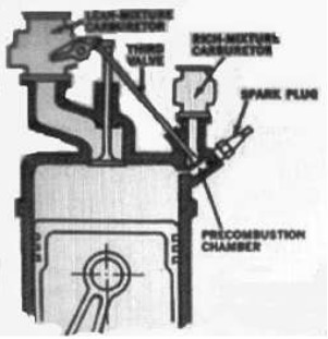
-A second version was carried out by request of the Aeronautical Service to avoid ignition in collector C.
-One system was to feed the fuel in continuous injection and with a rich mixture -the manifold was not so flammable.
-The proportion was easily adjustable, without having a classic carburetor.
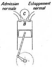
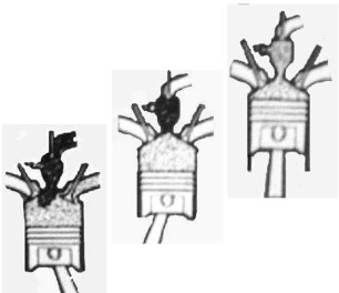
-Curiously, similar ideas appear later in various parts of the world, such as the pre-chamber system -being gasoline engines and not Diesel- that were tested by Chrysler.
-In this pre-chamber, the air-fuel ratio is from 16 to 22:1, a very rich mixture that will later be diluted with the poor mixture that arrives through the normal intake valve.
“Chrysler system”
-Another system is that of Brodersen Conta with pre-chamber and air valve.
“Brodersen Conta system”
“Nilov system”
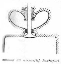
“Intake - Compression - Ignition”
-A rich mixture arrives through the pre-chamber and a lean mixture through the intake valve.
Engines of ROCHEFORT
Model: Multi fuel engine
Arquitecture:
Cooling:
Total Displacement:
Bore / Stroke: x
Power:
Weight: