

Updated: 19-Oct-2020
(See Turbodyne)
Turboprop engine 50% built between Northrop and Joshua Hendy.
-It had the XT-37 specification and was to deliver more than 5,000 shp. The works began in 1945.
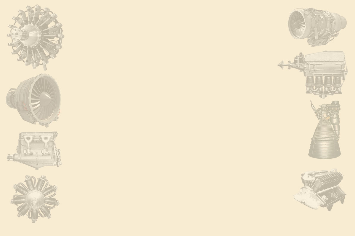
“Installation on a B-35”
-The engine was at the front, on the leading edge of the wing and had a 14-stage axial compressor and a two-stage turbine.
From Appendix 6: A great and powerful engine for the Army Air Force during WWII now appears.
-The Northrop-Hendy Co. was in Hawthorne, California. The engine became known as the Turbodyne (see main text).
-It could work with aviation gasoline, kerosene or pulverized coal.
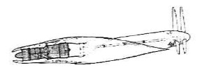
“The Northrop-Hendy Turbodyne” (PiP)
-Air enters through the bell-shaped intake on the right, is compressed inside the parallel cylinder and towards the middle of the engine it reaches the combustion chamber in an almost spherical shape, then reaching the turbine on the left.
-On this end we see the output of a shaft that would be for the propeller as shown in the main text.
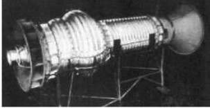
-Now the Turbodyne XT-37 on a test bench where it would deliver more than 10,000 shp.
“On a test bench with contra-rotating propellers”
-Northrop-Hendy designed a major turboprop that was to be installed on the EB-35 bomber plane, known as the Flying Wing. Both plane and engine project were abandoned after failing prototypes.
-In fact it was a turboprop with contra-rotating propellers, and a rear outlet with long transmission extensions up to the trailing edge of the wing. See main text.
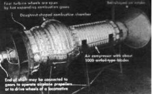
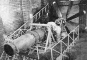
“New view of the Turbodyne turboprop”
-It is the same photo that is shown before, with added information.
Engines of NORTHROP-HENDY TURBODYNE
Model: Large Turboprop
Arquitecture: Turboprop
Compressor/s:
Combustion chambers:
Turbines:
Power / Thrust:
Weight: