

Updated: 21-Mar-2020
Around 19134, Charles L. Lawrance developed the Lawrance-Moulton Model A 8-cylinder V-engine in France. (see Lawrance-Moulton).
-In 1916-17 he created the Lawrance Aero Engine Company in New York City and started to build the model B V-8 engine, which had been designed in France.
-In the USA, it produces 3-cylinder and 9-cylinder radial engines, and horizontally opposed 2-cylinder engines.
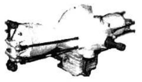
“Lawrance A”
-The Lawrance A, was an experimental engine that only gave 28 hp.
-Curiously, the crankshaft had a single rod bearing so that both connecting-rods and pistons went in one direction, not counteracting each other and causing vibrations, even so it was compensated by making the power strokes uneven, at 540° and 180°. (?).
-When the whole train of connecting rods and pistons went to one side, the engine went to the opposite side. The project was inconceivable in pure logic.
-However, in times of the Great War hundreds of these engines were manufactured, even under license by the Excelsior Motorcycle Co.
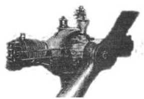
“Lawrance C2”
-Multiple horizontally-opposed, two-cylinder engines were made, such as the A, C, N series.
-The C-2 was the base for the A-3, still with 28 HP at 1,400 rpm.
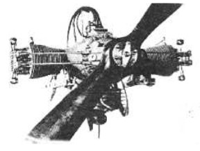
“Lawrance A3”
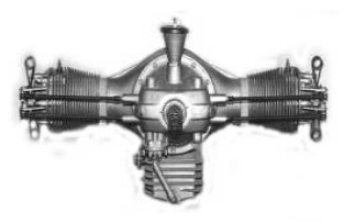
"Another view of the A-3"
-The N and N-2 models from the year 1917 already gave 40 HP at 1,900 rpm, displacing 121 cu. in. and following the formula with two horizontally-opposed cylinders.
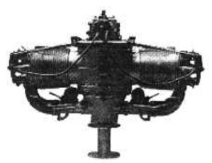
“N-2, top view”
-They had double ignition, the N-2 was intended for the NAVY.
-A version of these engines that was to be used in APU installations is shown below.
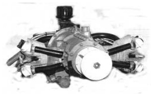
“Lawrance APU”
-The next major manufacturing line for Lawrance was the three-cylinder radial.
-Starting with the B model and the rest of the L series.
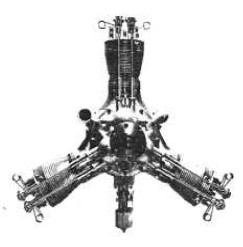
“Lawrance B”
-The B model is from 1916 and as we can see, the valve return springs are the same type as the A-3. It gave 60 HP.
Do not confuse this B model with the Lawrance-Moulton B model.
-The L series engines are started with the B. As a curiosity, the L-1 appears in an old edition of a prestigious publication such as “Lawrence”.
-Which led to error in the first edition of our publication. (see UFE chapters).
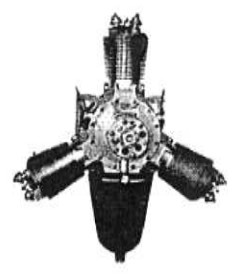
“L-1, front view”
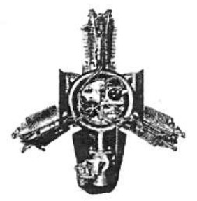
“L-1, rear view”
-The L-1 gave 60 HP at 2,100 rpm. We see that the valves already have normal springs. The oil tank is characteristic. Just behind it is the carburetor.
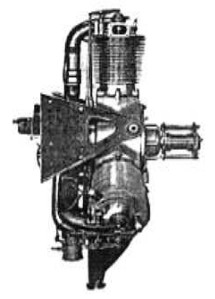
“L-1, side view”
-We retrieved a drawing of the 60 hp Lawrance L1.
-It has three radial cylinders and an oil pan in the central lower part, well visible. Just behind it, the carburetor.
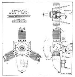
“Lawrance L1”
-The L-2, slightly more powerful, gave 65 HP at 2,000 rpm., With 223.44 cubic inches of displacement. It was from the year 1920.
-The cruising power was 56.5 HP at 1,600 rpm.
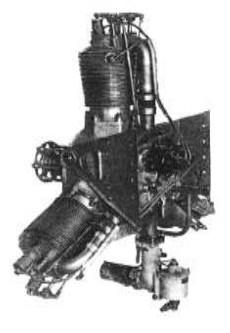
“Lawrance L-3”
-Impeccable view of the L-3 model that appears in a rear view image in the main text.
-Similar to L-1, L-2, L-4 and L-5. It also had three cylinders and gave 65 HP at 2,000 rpm.
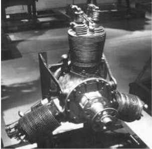
“Lawrance L-3 at the NASM”
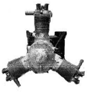
“Lawrance L-4S”
-The L-3 was an improved design of the L-2. It was from the year 1920.
-Of the L-4, it is known that it had similar values as the L-3.
-The L-4S version was installed on "Pony-Blimp" airships and on Sperry Messenger aircraft.
-It is mentioned that the L-64 was a direct derivative from the L-4.
-But it appears as a 5-cylinder radial.
-The L-5 was the last 3-cylinder model. This was in 1921.
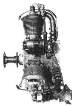
“Lawrance L-5”
-The L-64 that was presented as a derivative from the L-4 appears in the below photograph of a "vintage" aviation organization.
-The only one with 5 cylinders. The normal ones had 9 cylinders, J and R series.
-It is commented here that during the 1930s-40’s, Lawrance evolved into Lawrance Engineering & Research Corp., moving to Linden, NJ.
-From this time are the L-64 and the previous twin-cylinder APU.
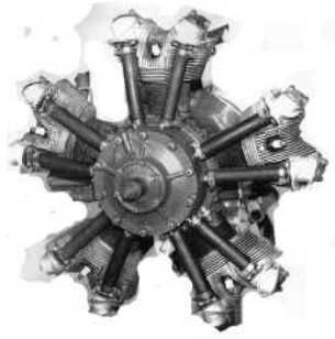
“L-64”
-The J engines were destined for the US Navy while the R were for the US Army.
-They turned out to be engines of success. Both with nine cylinders.
-The 1920 J-1 gave 220 HP at 1,800 rpm with 727 cu. in. and it was the first major radial engine contract signed by the US Navy.
-The R-1 for the Army was somewhat smaller with a displacement of 675 cu. in. It gave 150 HP at 1,600 rpm.
-J-2, from the year 1922 gave 250 HP.
-It turns out that in 1923 Charles Lawrance sold his company to the Wright Aeronautical Corp, becoming its director until 1930.
-In this period the J-1 evolved as the Wright J-4, J-5 and J-6 also known as "Whirlwind".
-It is said that in the J-1, Wright provided him with cylinders for the AS Jaguar, becoming the J-5 used by Lindberg in the "Spirit of St. Louis" and known as the Wright Whirlwind J-5.
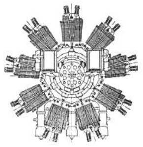
“Lawrence J-1, drawing”
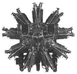
“J-1, front view”
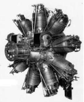
“Nice view of the J-1”
-We see the magnetos mounted on some bases at the front of the engine.
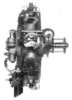
“J-1 side view”
-In the year 1924, some dossiers with the numbers 3137 / 452.8 and 3208 / 452.8, referring to the L-4 and an unknown T-2 (Twister?), were introduced in the USNA registry.
-We know about their APU constructions until WWII.
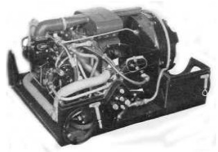
“APU (APP) Lawrance 30C2”
-Included in a suitcase for on-board installation, shown without top cover. It acts as a 15 HP electric generator.
-There was the 30C5 model for ground operation (APU) that was not soundproof.
-The D, D-1 series were also placed in a suitcase. These 4-stroke engines had two air-cooled cylinders. They gave 5kW at 28.5 VDC.
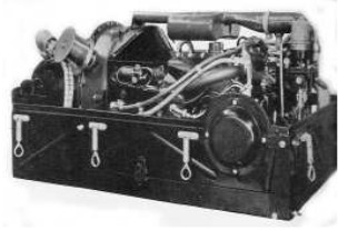
“Lawrance 30D series (30D-1)”
-The 20A model is another APP in appearance similar to the previous one but without a soundproof case.
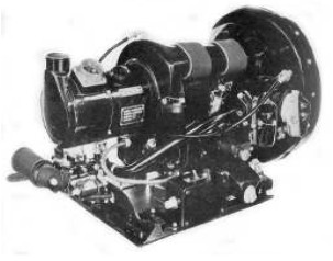
“”Lawrance 20A”
-The 75B model is more original since it has one of Lawrance's own 5-cylinder radial engines.
-They had 8-30 VDC voltages, depending on the generator. The engine power was 37.5 HP.
-It was in an upright position, which was unusual. Locked in its cylindrical suitcase, it looks like a barrel.
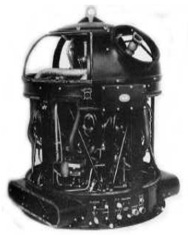
“Lawrance 75B”
-New photograph of the A-3 with propeller.
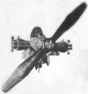
"The A-3, see the valve springs"
From Appendix 7: The Lawrance 75B of the main text is coupled into an auxiliary group of APP energy.
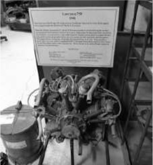
"Lawrance 75B engine belonging to an APP"
-It was designed by Charles A. Lawrance in 1941. It was used on B-32 and Consolidated PB2Y3 Coronado Flying Boat as well as some Navy airships.
-It gave 37.5 HP and had five radial cylinders, providing sufficient electric current to start the aforementioned poly-motors and emergency electric power. It could deliver 8 kW at 30 Volts.
-It included a fan, a Stromberg carburetor and two Scintilla magnetos.
-This engine was considered a successor to the J-5 and was Charles's last project. The photograph above has been taken at the San Diego Museum in California.
-En el Museo “Power of the Past” se ha localizado otro Lawrance aplicado a un grupo APU.
-An other Lawrance applied to an APU group has been located in the “Power of the Past” Museum.
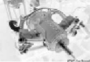
“Lawrence's engine for APU use” (PiP-AEHS)
“And the same engine for flight” (PiP-AEHS)
From Appendix 10: We found a source of information with new clearer pictures of engines already described in the main text.
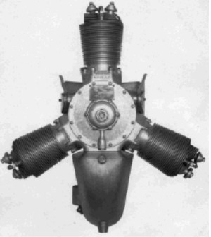
“Lawrance L-1”
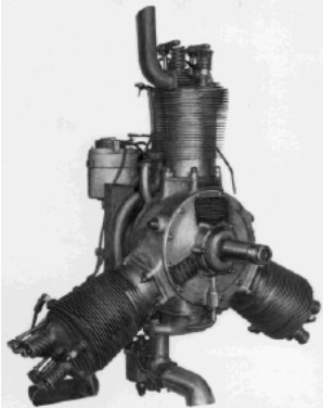
“Lawrance L-4”
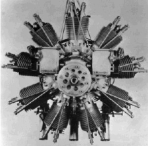
“Lawrance R-1”
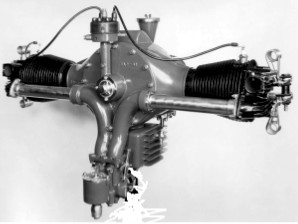
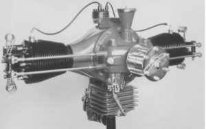
“Two views for the Lawrance A-3”
Engines of LAWRANCE
Model: APU’s
Arquitecture:
Cooling:
Total Displacement:
Bore / Stroke: x
Power:
Weight:
Model: Model A, A-3
Arquitecture: 2-cylinder Horizontally opposed
Cooling:
Total Displacement:
Bore / Stroke:
Power: 28 HP @ 1400 rpm
Weight:
"Lawrance A-3, half-front view"
Model: Model B
Arquitecture: 3-cylinder Radial
Cooling:
Total Displacement:
Bore / Stroke:
Power: 60 HP
Weight:
"Lawrance B"
Model: Model C-2
Arquitecture: 2-cylinder Horizontally opposed
Cooling:
Total Displacement:
Bore / Stroke:
Power: 28 HP @ 1400 rpm
Weight:
"Lawrance C2"
Model: Model J-1
Arquitecture: 9-cylinder Radial
Cooling:
Total Displacement: 727
Bore / Stroke:
Power: 220 HP @ 1800 rpm
Weight:
"Lawrance J-1, front view"
Model: Model J-2
Arquitecture: 9-cylinder Radial
Cooling:
Total Displacement:
Bore / Stroke:
Power: 250 HP
Weight:
Model: Model L-1
Arquitecture: 3-cylinder Radial
Cooling:
Total Displacement:
Bore / Stroke:
Power: 60 HP @ 2100 rpm
Weight:
"Lawrance L-1, front view fig.2"
Model: Model L-2
Arquitecture: 3-cylinder Radial
Cooling:
Total Displacement: 223.44 cu. in.
Bore / Stroke:
Power: 65 HP @ 2000 rpm
Weight:
Model: Model L-3
Arquitecture: 3-cylinder Radial
Cooling:
Total Displacement:
Bore / Stroke:
Power: 65 HP @ 2000 rpm
Weight:
"Lawrance L-3, NASM"
Model: Model L-4
Arquitecture: 3-cylinder Radial
Cooling:
Total Displacement:
Bore / Stroke:
Power: 65 HP @ 2000 rpm
Weight:
"Lawrance L-4S"
Model: Model L-5
Arquitecture: 3-cylinder Radial
Cooling:
Total Displacement:
Bore / Stroke:
Power:
Weight:
"Lawrance L-5"
Model: Model L-6, -64
Arquitecture: 5-cylinder Radial
Cooling:
Total Displacement:
Bore / Stroke:
Power:
Weight:
"Lawrance L-64"
Model: Model N, N-2
Arquitecture: 2-cylinder Horizontally opposed
Cooling:
Total Displacement: 121 cu. in.
Bore / Stroke:
Power: 40 HP @ 1900 rpm
Weight:
"Lawrance N-2, top view"
Model: Model R, R-1-
Arquitecture: 9-cylinder Radial
Cooling:
Total Displacement: 675 cu. in.
Bore / Stroke:
Power: 150 @ 1600 rpm
Weight:
"Lawrance R-1"