

Updated: 17-Oct-2018
The "Typ A" was developed by the "Forchunginstitut für Kraftfahrwesen" in 1941-42, under the orders of Professor W. Kamm.
“Typ A”
-It was a multiple radial polygon engine as a result of joining 4 V-12 engines around a single box.
-It produced 1400 kW. It had Hirth HM-512 as reference).
-Other designs were the "Typ B" giving 2360 kW. and the "Typ D" delivering 4400 kW. (6,000 CV).
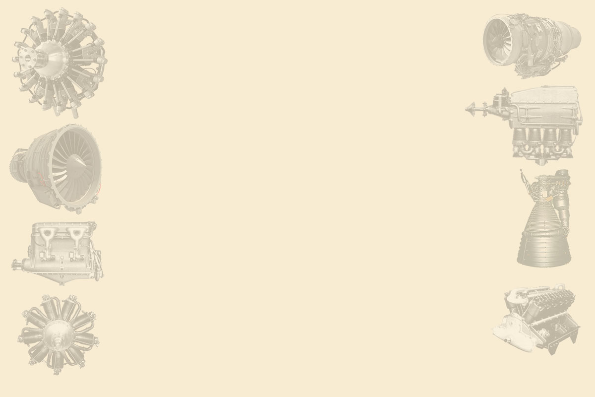
From Appendix 9: We have new information about the "Type A" in which it is indicated that it has 48 air-cooled cylinders as it is the coupling of four Hirth HM-521C engines. Below we show a new picture.
“Typ A side-front photo”
-The "Typ B" was water cooled and had 32 cylinders in four banks of 8 cylinders.
-The FKFS is a center for automotive research and aviation engines. The Typ A engine was designed and manufactured between 1941 and 1942.
-The FKFS is the "Forschngsintitut für Kraftfahrwesen und Fahrzeugmotoren", dependent on the University of Stuttgart. Today it is dedicated only to motorsports, including design and aerodynamics.
“Otro motor de piston experimental “
-This engine takes the exhaust from the cylinders to turbines that are added to the crankshaft. That is a "compound" system and besides, instead of a propeller, it has a double fan.
-In the main text we have learned that the engine Typ "A" was composed of four Hirth engines (cylinders) model HM-512. In total it had 48 cylinders.
-The "Typ B" had 32 cylinders, and was made of four Hirth 8-cylinder engines.
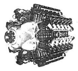
“FKFS made of four 12-cylinders” (PiP)
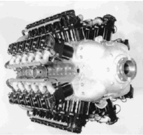
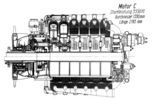
-The "C" had four Hirth engines attached in a block, but each with its own crankshaft leaving a hollow passage in the center of the engine that could be used for a possible weapon.
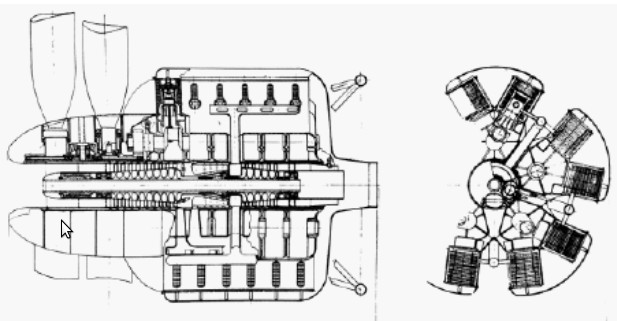
"Typ C schematic diagrams" (PiP)
"Another cross-section front view for the "Typ C"
(Illustrations due to Kevin Kemmerer = PiP)
-It seems that the engineers of this design group were also "recruited" within the operation "Paperclip" (hunting of German talent sent to USA). Like Krater and others.
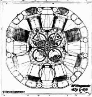
-It also seems that, while the first designs were made during WWII, the 60-cylinder model shown was made around 1955. There is no evidence that it entered
in production.
-It was a coupling of five 12-cylinder Hirth engines, (5 x V12), with a total of 60 cylinders.
-In the central part of the engine there was a "Compound" system, in which the exhaust gases gave kinetic energy to the propellers and to the supercharging compressors.
-To absorb the generated power, two coaxial contra-rotating propellers were used.
-Perhaps there was also a residual thrust of the gases backwards and diluted with the cooling air for the cylinders.
Engines of FKFS
Model: Experimental mixed compound 60 cyl.
Arquitecture: 60-cylinder
Cooling:
Total Displacement:
Bore / Stroke:
Power:
Weight:
Model: Experimental mixed compound-fan, “X” 32 cyl.
Arquitecture: 32-cylinder X-engine
Cooling:
Total Displacement:
Bore / Stroke:
Power:
Weight:
Model: Typ A
Arquitecture: 48-cylinder Radial
Cooling: Liquid
Total Displacement:
Bore / Stroke:
Power: 1400 kW
Weight:
"FKFS Typ A fig. 2"
Model: Typ B
Arquitecture: 32-cylinder Radial
Cooling: Liquid
Total Displacement:
Bore / Stroke:
Power: 2360 kW
Weight:
Model: Typ C
Arquitecture: 48-cylinder Radial
Cooling: Liquid
Total Displacement:
Bore / Stroke:
Power:
Weight:
"FKFS out of four 12-cylinder engines" (PeT)