

Updated: 08-Oct-2020
After WWII, the Cameron Aero Engine Corporation made one of the few American inverted inline engines of the time.

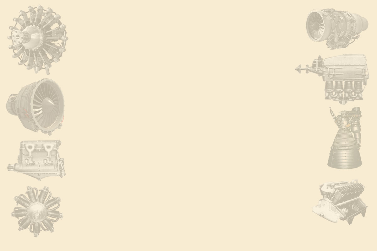
"Cameron C4-I-E1"
-The C4-Y-E1 from 1946 with its four inverted inline cylinders had a displacement of 301 cu.in. and gave 125 hp.
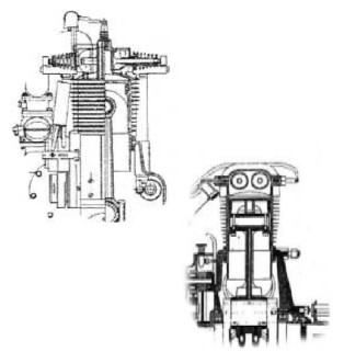
-Before the war, in 1928, when it was called "National Aero Corp" it made the 60 hp engine with the same arrangement, and the 7-cylinder radial engine that gave 100 hp.
-Returning to the illustration, the 125 hp power output was achieved at 2,500 rpm, while at cruise speed they gave 110 hp at 2,200 rpm.
-Like in German Zündapp engines, the opposed valves in the cylinder heads needed the camshaft divided into two, one on each side of the engine.
-They were one of the first to use magnesium crankcase in the USA. These engines used an injection carburetor, that is, a mixture of carburetor and injection system called "Bendix-Stromberg Pressure Diaphragm Injection”.
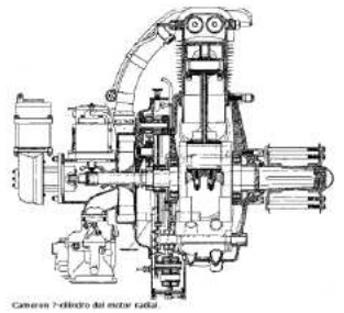
-In relation to the picture of the Cameron engine with inverted cylinders and laterally arranged valves.
-There are two more designs for air-cooled engines around 1929.
-These engines were designed by Everett Cameron and built by the National Aero Corp.
-One engine was an upright four-cylinder giving 60 hp. This was the first Cameron, apparently.
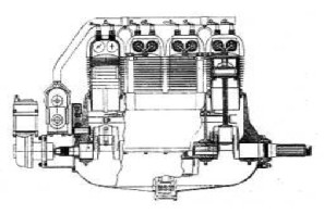
"Cameron, 60 hp"
-The originality of this engine was that it had four valves per cylinder but located horizontally, two on each side. The valve actuation device by camshaft was original.
"Cross-section for Cameron cylinders"
-There was a version of a seven-cylinder radial engine that gave 100 hp. We can clearly see the side valves in each cylinder head, in twos.
-Presumably this system would present an engine with a smaller front area.
"Cameron radial"
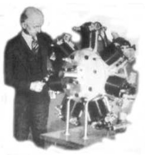
"Edward Cameron with his radial"
From Appendix 10: Formerly it was National Compression and Aero Compression. Designs of aviation engines were due to Edward Cameron.
-The 7-cylinder radial engine, of which we now have more illustrations, had a characteristic that distinguished it from its congeners: The position of the two valves in the cylinder head.
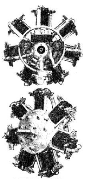
"Two views for the Cameron radial engine"
-The design is from around 1928. It seems that there are several valves per cylinder head. Two intake and one exhaust.
-It gave 100 hp at 1,800 rpm.
"Cameron radial engine diagram"
Engines of CAMERON
Model: 60 HP, in line, 4 cils.
Arquitecture: 4-cylinder In-line
Cooling:
Total Displacement:
Bore / Stroke:
Power: 60 HP @ rpm
Weight:
It had four valves per cylinder but they were placed horizontally, two on each side.
"Cameron, 60 HP"
Model: 60/100 HP, radial de 7 cils. (ver National Aero
"Cameron radial"
Model: C4-I-E1, 125 HP
Arquitecture: 4-cylinder In line inverted
Cooling:
Total Displacement: 301 cu. in.
Bore / Stroke:
Power: 125 HP @ 2500 rpm
Weight:
It had a max. power output of 125 hp at 2,500 rpm, while at cruise speed it gave 110 hp at 2,200 rpm.
"Cameron C4-I-E1"