Updated: 09-Jan-2020
SECOND PART
(Go to Argus first part)
-The 411-A1 version, similar to As-410, had a reduction gear at a different ratio, and gave more power for its higher rpm. It gave about 600 CV at 3,300 rpm.
-The 440 and 600 CV As-411s were built under license by Renault during the war, and they continued building them after the war.
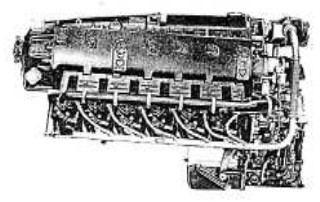
"Argus As-411"
-The As-412 y As-413 were prototypes designed in cooperation with Junkers.
-They were water-cooled, 24-cylinders H-engines with contra-rotating propellers. They did not pass the projecting stage.
-We now have information about the AS-7 radial engine that does not appears in the main text.
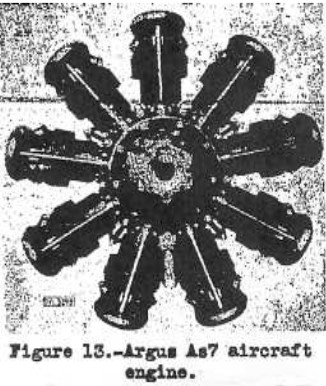
-It is a radial engine with 9 cylinders from 1927. Its power was 800 CV at 1,850 rpm.
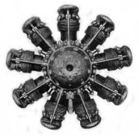
"Argus As-7"
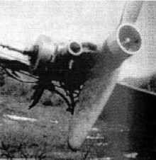
-A curiosity: Bruno Nagler made some small helicopters having an original propulsion system. The NR-54 V2 models, as shown below, had a small Argus ZF-140 single-cylinder engine driving the main rotor blades.
-They gave 8 CV each and were simple. Presumably, the centrifugal forces caused malfunctions. But once again they made a necessary test to reach what today exists as reliable.
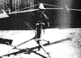
"The NV 54 V2"
-And we have the engine below. In the NASM there is another helicopter of the same designer, but somewhat larger, although it is a single seater like the one before.
"Argus ZF-140 engine"
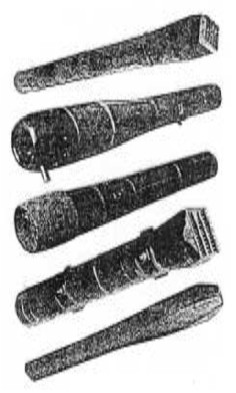
-Other notorious Argus engine was the one that was created by Argus-Schmidt-Rohr, the Type 109-014. It was the pulsejet that powered the V-1 flying bomb. Tests were made even before the war with several prototypes.
"5 pulsejet prototypes"
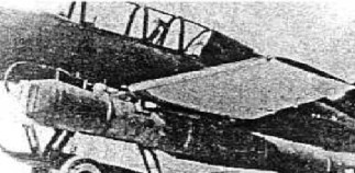
We can see the first one installed under a wing of this Me-328.
"Argus on Me-328"
"Argus on Go-145"
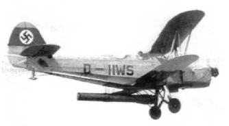
-Another test model was the Argus reference VSR-9a pulsejet that we can see under a wing of the Gotha Go-145. (the last two letters SR stand for Schmidt-Rohr that took part in these engines).
-The second model shown in the prototype series is very similar to that was used by the V-1 shown below.

"Argus 109-014"
-They were made with simple recoverable materials, these "propulsive ducts" were welded in different diameters, and these sections were very easy to manufacture.
-The total length was about 3,350 millimeters and the operating principle was already known through the trials of the Frenchman Lorin.
-At the front of the engine was a set of inlet shutters (working like harmonica blades) and it also included a battery of fuel injectors.
-In the central part was the combustion chamber with a spark plug for starting and on the rear a sufficient long resonance tube.
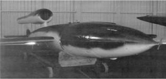
"The V-1 at the MAE-Le Bourget"
-Launched by catapult, by rocket assistance or by the Walter steam generator (hydrogen peroxide), the V-1 missile (Fieseler Fi-103) affected the air intake that became mixed with the fuel and ignited. These V-1s were also airdropped by modified bombers.
-Expansion occurs behind the exhaust nozzle and because of the inertia of the gases it creates a vacuum in the chamber that starts a new fresh mixture intake, igniting again through the existing temperature.
-This occurs around 45 times per second delivering about 300 kgs of thrust. (Cruise equivalent to 650/700 hp)
-Besides this application, of which is known that over 31,000 pulsejet engines were made. Tests were made on fighter aircraft like the glider Gotha Go-345, or He-162B among others.
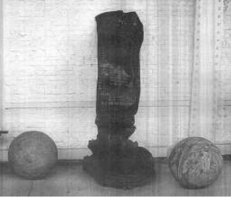
"Motor aplastado"
-The photograph of a flattened engine belongs to the exhibition at the Brussels Museum. It certainly did not explode and the engine had fallen almost vertically and folded. Next to it, the spheres of compressed air that gave pressure to the fuel tanks.
-Already in 1943 they studied engine combinations of pulsejets with ramjets, like the ones below. The first one, the 109-014 in position to let the exhaust end up in a ramjet body, creating a "magnifying horn" that will make the air circulate and a second combustion is created. And the same happens with the 109-044 version, which had a square intake.
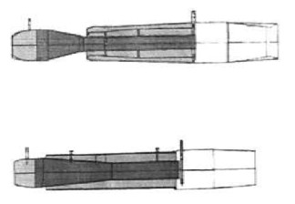
"Two pulse-ramjets"
And another postscript, we repeat the 80 CV Argus As-8 below since in the first 2008 edition the picture in the main text was somewhat blurred. What stands out is that the magnetos are installed at the engine's front.
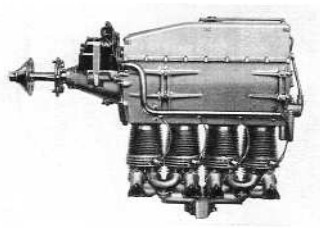
"Argus As-8 left side without deflectors"
-Another engine that is certainly Argus too, considering the overall architecture of the engine, is shown below. But this is the one that gives 110 hp,
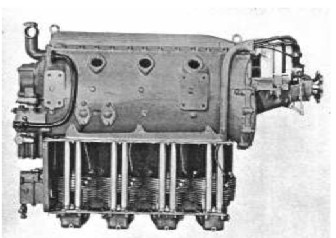
"Argus 110 CV"
-We observe a difference in the mounting system: shape and the place for the plane's bedplate.
-As it is mentioned in the main text, during Argus' second period, their engines were known by their power as well as by the two letters As.
-The 120 hp engine at the Museum in Zurich, Switzerland, is an As-II? We recognize it as the 120 CV in the main text.
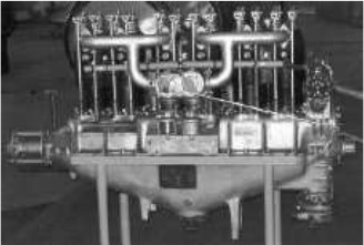
"Argus As-II?"
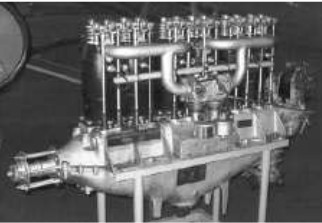
"Argus As-II?, another view"
We observe that the two front legs are broken or cut.
Author's note: The As-II reference of this engine does not match the standard identification of Argus in the first period: WWI when the engines were designated as Type I, II, III etc.
-Note that in the second period, which would be WWII, the engines were identified as the Argus As-6, 8, 10, etc. Therefore we assume this is a misidentification of the museum, although we continue investigating.
-Another visit to the Regia Aeronautica Museum has allowed us to photograph the Argus As-10c.
-Beautifully restored with its original bed.
-The photos are courtesy of our collaborator JGB.
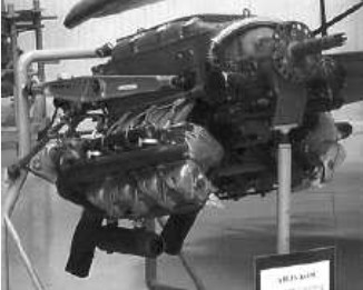
"Argus As-10c at Vigna di Valle"
-At the Krakow Museum we found the Argus As-5. A huge 24-cylinder engine that gives 1,500 CV at 1,800 rpm, with a displacement of around 94 liters and weighing 1,100 kg.
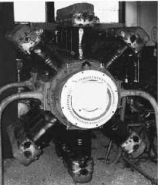
"Argus As-5 engine"
-As we can see there are two W-engines linked by the same crankshaft, one engine above the crankshaft and the other one inverted below it.
-It seems that it is Riedel's design, the engineer who made the fast 2-stroke starter for Junkers, BMW and Heinkel-Hirth turbines.
We have found a hitherto confidential report (the NACA Technical Memorandum No.706) with an Argus AS-7 silhouette of a 9-cylinder radial that is mentioned in the main text but without any known architecture.
-The tiny Argus ZF-140 with 8 CV had been rediscovered on the small Nagler-Rolz helicopters. Each engine has its small propeller.
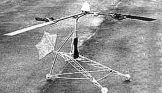
"AS-8 engines halfway the blades"
-NR helicopters were designed by the Austrian Bruno Nagler (NR = Nagler Revoplane). He made tests with more powerful engines but returned to the Argus 8 CVs. This was in the 1930's.
-In 1942, the Heliofly III-57 was very complex. It had two single blade rotors that were contra-rotary and on each blade there was an Argus 8 CV engine that acted as counter-balance. The III-59 had 16 CV engines.
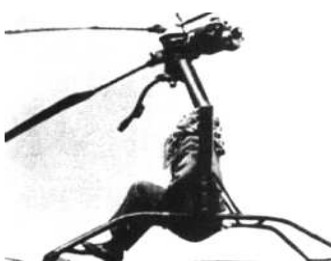
"Heliofly with Argus"
-This information about Nagler and Heliofly appears in the book "German Aircraft of the Second World War" (out of stock) and much more information.
-In 1942 there has been made a portable version based on the Heliofly that was also designed by the Austrian engineer Paul Baumgartl.
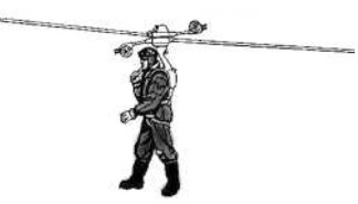
"Personal appliance with two Argus AS-8"
-The engine below is a smaller and simpler Argus pulsejet model than that was used in the V-1.
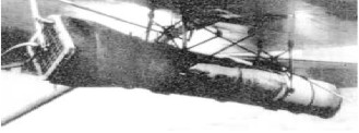
"Argus under a wing with manual control"
-During WWII, they also made BMW-801 engines at the factory in Berlin.
From appendix 9: The 100 CV, 4-cylinder, inline engine, is exhibited in the Munich Museum, with a cut propeller and a magnificent water radiator.
-All exhibited like a car by inertia of those days.
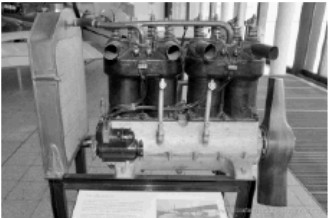
"Argus 100 CV assembly" (E. V.)
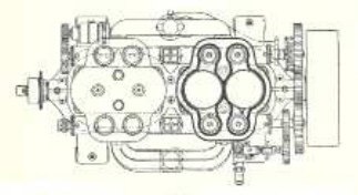
"Argus for Airships"
-The 75 CV of power was reached at only 800 rpm. The engine's weight was 370 kg, which gives a weight/power ratio of almost "5". Some years later it would decline to "1".
-An aircraft with two double-mounted Argus 100 CV, four-cylinder, inline, upright engines.
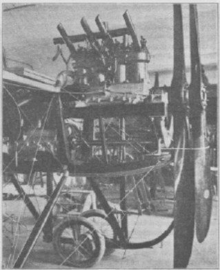
"Airplane with a propulsion designed by Loutzkoy"
-It turned out to be the Rumpler Taube single-engine, the most powerful at that time. It had coaxial propellers that were spinning in the same direction. The rear one had a larger diameter than the front one.
From Appendix 10: The Ace-7 radial engine exhibited at the Museum of Krakow (PL) shows us an interesting detail.
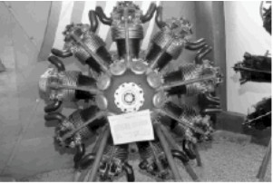
"As-7" (Photo E. Vseteka)
-Besides that it only has one rocker cover, there are other small ventilation? covers at the front of the crankcase between each cylinder. We assume they are.
-Except at the lower part that in the previous photo is covered by the museum card. There it matches the oil sump.
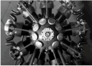
"The As-7 without the visual obstacle"
Photo of the mounting of two Argus-Schmidt-Rohr pulsejets on the Me-328.
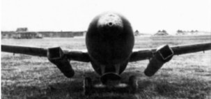
"Front view of pulsejet installation"
(See Paul Schmidt and Schmidt-Rohr) We bring here the Argus 109-014 version installed on an R4 manned project V1.
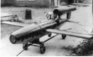
"The Argus looks the same as the normal V1"
-At the bow of this manned flying bomb there is room for an anti-aircraft bomb, as we see below.

"V-1 type R4 with bomb ready" (PiP)
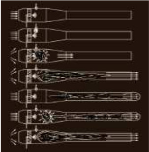
"Pulsejet operating principle"
-We have seven engine operating arrangements. In the first and second fuel is injected having the spark plug working before. There is a fuel explosion closing the shutter valves at the front entrance and the expansion exits toward the free way toward the rear.
-Like a gas-piston this creates a vacuum in the chamber that opens the shutters again entering the air that is necessary for the next combustion. The process is repeated about 45 times per second. The design - the tailpipe lengths - determine the cycles per second, along with the amount of fuel injected.
-Several new illustrations on different models and powers of Argus engines.
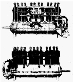
"Argus 150 CV 6-cylinder engine"
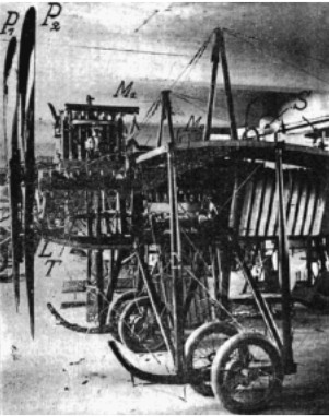
"Two Argus 100 CV engines at different levels driving two propellers"
Engines of ARGUS 2nd Part
We have no more detailed engine information for this brand. We continue our search. Any help will be appreciated.
