

Updated: 08-Jan-2020
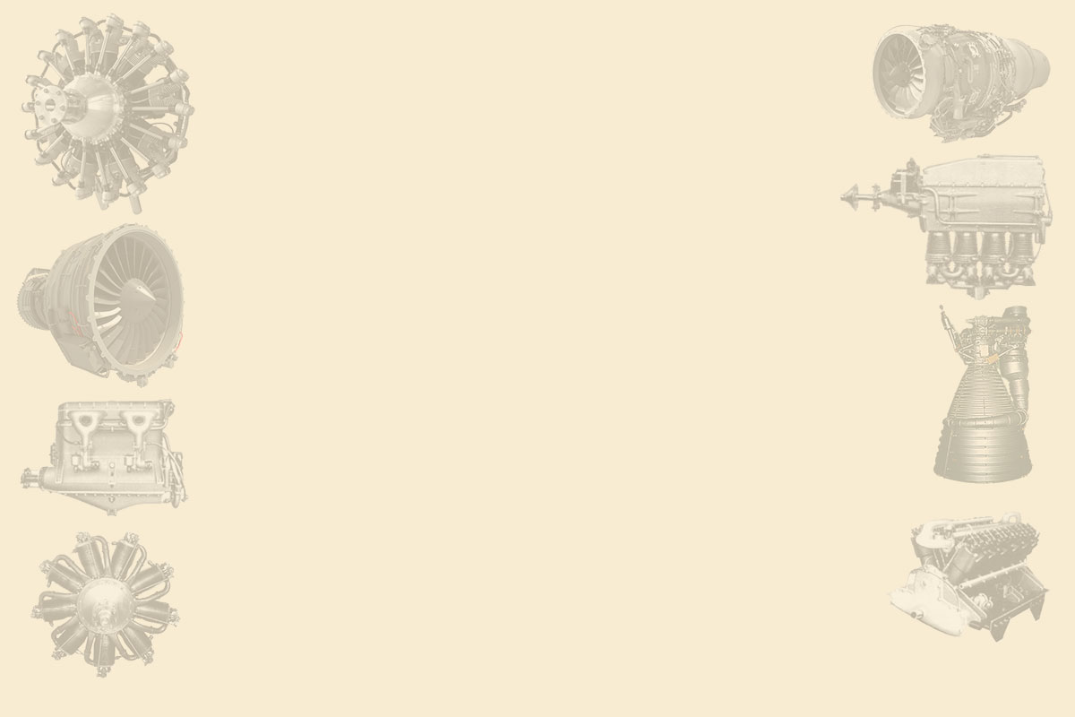
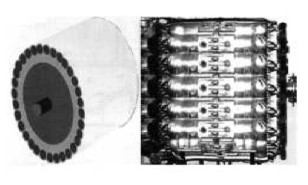
Barrel type engine displayed at the Smithsonian Museum. It has 18 cylinders in two groups of 9 horizontally opposed cylinders.
-This was the 4th prototype. Almen was located in Seattle, Washington.
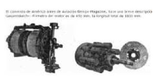
-This engine model was the A4 and dates back to 1920. The small frontal area together with its 425 hp was one of the advantages of this system.
-Below we show another illustration from 1921 with the engine seen from behind. It is said that a gun could be installed inside the motor shaft.
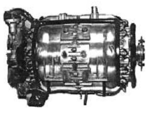
"Almen, 1920 y 1921"
-You can find more information in the US National Archives, "Sarah. B. Clark" with number 3105/452.8.
-A new picture of the Almen barrel engine as exhibited at the NASM.
-These engines were designed between 1921 and 1925 by J.O. Almen and developed in collaboration with the US Army Air Service.
-It seems that there were several models. The model shown here is the A-2.
-The A-3 and A-3a models had constructive improvements.
"Almen, model A"
"Almen diagram"
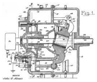
-In this publication there is enough information on this barrel engine but there are still appearing new illustrations such as the patent applied for by John O. Almen.
-Here in the simplest form, liquid-cooled, normal swash plate, it looks like some kind of a "spider".
"Patent engine diagram"
-Engines that were implemented had a double swash plate and double-piston cylinders. "Wabbler Kinematics"
-But in a great imagination exercise, Almen designed an engine with a big amount of cylinders, without doubt aiming to obtain high powers.
"A powerful imaginative Almen mounting"
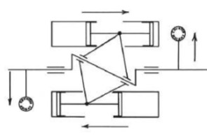
-We received more information about this characteristic barrel engine, models A-1 and A-4.
-Unlike other engines of this type, it has a central inclined disk and therefore it does not use the common combustion chamber for every two cylinders, that are doing other engines of this type.
-Schematically it can be represented as follows:
"Wabbler Kinematics"
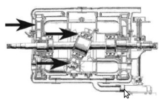
-Implemented, in the A-1 it was defined as follows.
"Almen A-1 schematic diagram"
-More information about the evolution of Almen models are described in the main text.
-The illustrations in this extension come from the "Aircraft Engine Historical Society", from an article by its President Kimble D. McCutcheon.
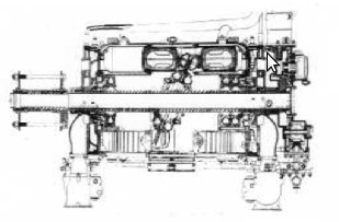
-To compare the differences between the A1 and the A-4 in 1924, we offer a cutaway diagram of the latter engine.
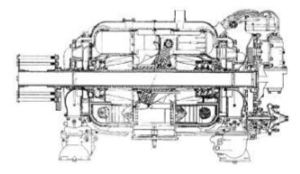
"A-4 cutaway diagram"
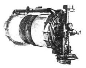
-And a photograph of the full outside.
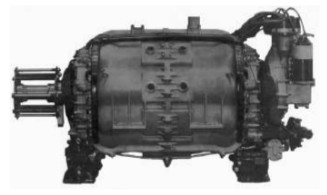
"The Almen A-4"
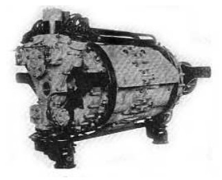
From Appendix 10: Photos from the German "Flugsport" magazine from before WWII, showing the revolver engine assembly, and without the cover next to the oscillating plate.
“Uncovered Almen engine details” (PiP-Flu)
Engines of ALMEN
Model: A-1
Arquitecture: 18-cylinder Barrel
Cooling:
Total Displacement:
Bore / Stroke:
Power: @ rpm
Weight:
Model: A-2
Arquitecture: 18-cylinder Barrel
Cooling:
Total Displacement:
Bore / Stroke:
Power: @ rpm
Weight:
Model: A-3, A-3a
Arquitecture: 18-cylinder Barrel
Cooling:
Total Displacement:
Bore / Stroke:
Power: @ rpm
Weight:
Model: A-4
Arquitecture: 18-cylinder Barrel
Cooling: Liquid
Total Displacement:
Bore / Stroke:
Power: 450 @ rpm
Weight:
The A-4 dates back to 1920. The small frontal area together with its 425 hp was one of the advantages of this system.
"Almen A-4"