

Updated: 06-Dec-2019
Perhaps it was the first genuine rotary engine built successfully in the USA, after several trials, including on railway wagons.
-They were variants of the Adams Farwell three-cylinder automotive rotary engines from 1903.
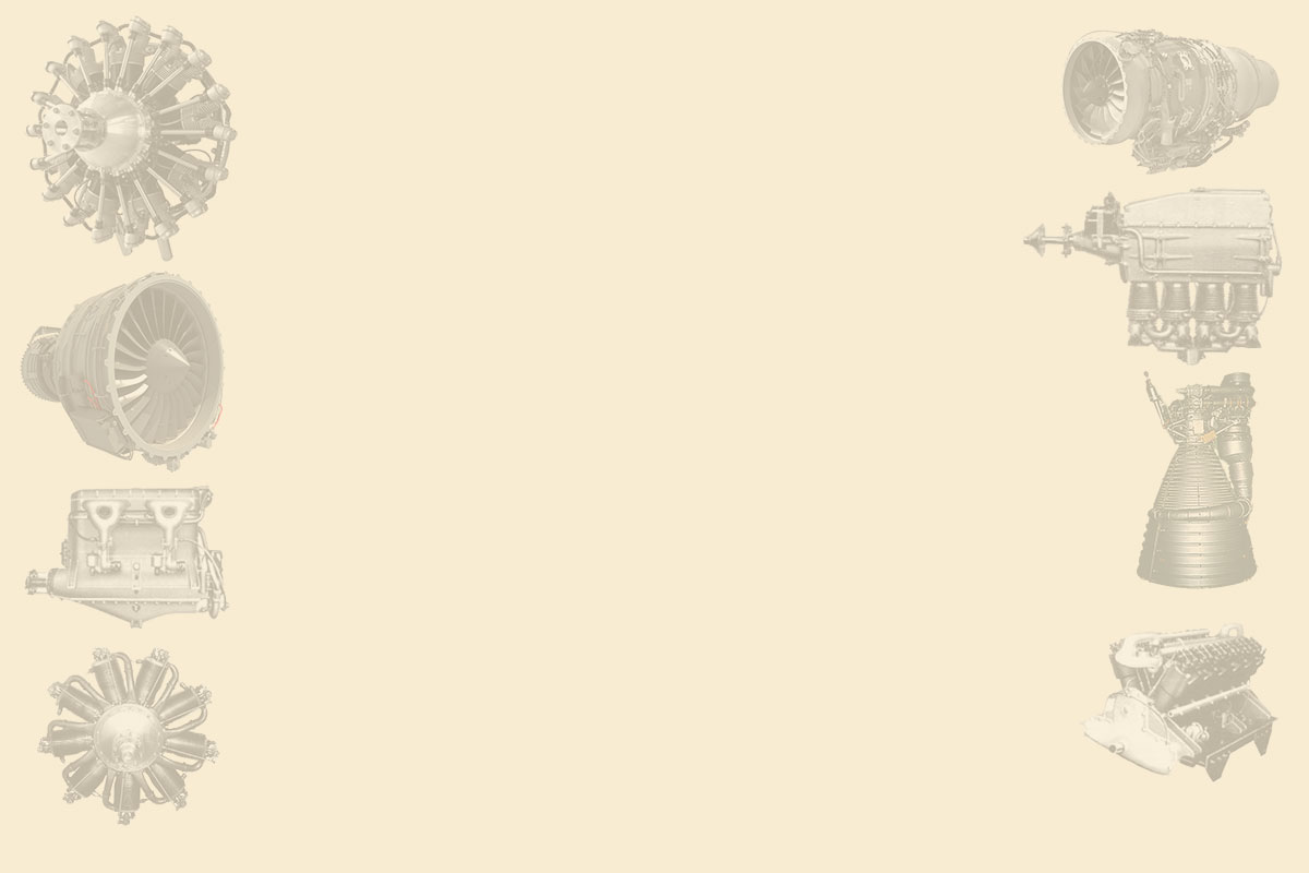
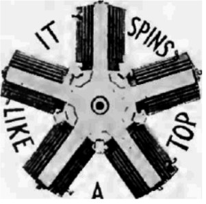
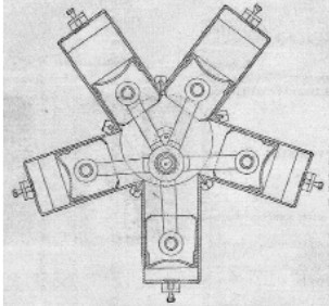
-The five-cylinder engine called KM11, is shown below.
“Adams Farwell, vertical”
-This engine gave 50 hp with variable compression so that it could maintain more power at higher altitudes. (This appliance was also used by Gyro Eng. Co).
-The adaption of this engine is due to engineer Mr. Moore.
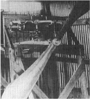
-It was vertically installed in the "Berliner" helicopter around 1907.
-Adams Farwell engines were increasing in power according to the demands of aircraft manufacturers, to the point where the engine's gyroscopic forces interfered with the aircraft control.
-A final design was installing contra-rotating propellers to prevent it.
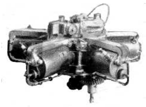
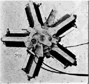
-The best known operating Adams Farwell rotaries began with an engine that gave 36 hp at 1000 rpm, with five cylinders, being able to reach a maximum of 1500 rpm.
-They had a displacement of barely 250 cu in.
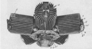
"Adams Farwell 5 cylinders"
-The Cylinder fins were along them and not around them, knowing that the air-drafts, due to the the centrifugal action, were from the center to the periphery.
-Equally, the valves had no springs since the centrifugal force ensured its settlement.
-A single push-pull rod moved the two valves for each cylinder.
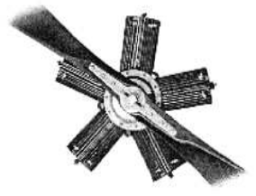
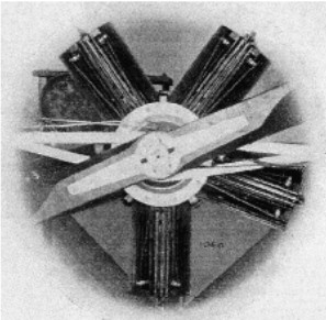
"Adams Farwell 6-cylinder"
-The 63 hp model with five cylinders gave its power at 800 rpm, being able to reach 1,200 rpm. With a total displacement of 621 cu. in.
-The 55 hp engine was an enlarged design of the first one with a displacement of 541 cu in.
-If the former models had a horizontal crankshaft. the first not-experimental rotary with a vertical crankshaft was a five cylinder engine with 72 hp and was developed to reach even more power.
-The bi-rotary engine had six cylinders and gave a power of 280 hp.
-In the picture we can see the layout of the alongside fins.
-The crankshaft rotates at 1,500 rpm, driving a propeller with a low pitch while the cylinders rotate in the opposite direction at 1,200 rpm, driving another propeller with a higher pitch.
-There were designs with ten, fourteen and eighteen cylinders of this brand. In 1929, Moor founded the General Airmotors Corp. to manifacture a fixed radial engine with variable compression that gave 125 hp.
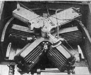
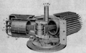
-We offer a better view of the engine that was designed by the Adams Farwell company at Dubuque, Iowa in 1907. It was used for experimental helicopters designed by Berliner and Newton Williams.

“Adams Farwell at the NASM”
"The same engine on a work bench"
It is the 36 hp vertically mounted rotary engine that runs at 1,500 rpm with five cylinders and a normal aircraft transmission.
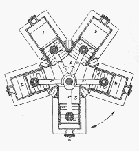
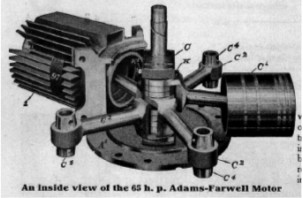
-From appendix A7/6: A new illustration of an Adams Farwell rotary engine in which we can see more of its construction details.
"The 5-cylinder Adams Farwell"
-These engines have the characteristic longitudinal cylinder fins.
-Because of its horizontal position between a possible chassis and a chain drive, it should be a land vehicle.
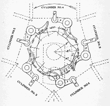
-From appendix 9: A new image of a rotary engine cross-section diagram.
"Rotary cross section"
-The area around the cylinders, with the fins that are longitudinal in this engine.
-See the examples in the main text.
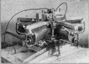
-In spite of the design's apparent simplicity, below we will see the cam plate for the valve rods.
"Details of the cam plate and controls"
It is curious that they use shoe-shaped cam followers instead of rollers.
From appendix 10: We have new pictures of these radial rotary engines. The first picture is taken from a brochure and shows an Adams Farwell air-cooled engine. Another picture is taken from a maintenance manual for the same engine, but water-cooled. And then another curious photograph of two engines that are held by two mechanics while one of the engines is running.
"From an Adams Farwell brochure"
"Liquid-cooled Adams Farwell engine"
-The two engines are on a frame held by two workers. The engine on the right is running and the one on the left is not, so demonstrating the low level of vibration and torsion.
-The two engines are liquid cooled.
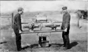
"Two engines on a frame"
-We continue with this brand's engine information (The Addams Company) found in the "Aeronautics" magazine from 1911 (USA).
-The company started to build land vehicles in 1898 and around 1903 they installed a radial rotary engine in a cage. The engine spinned along with the wheels, being front-wheel drive.
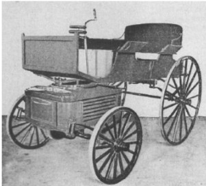
“Automobile with Adams-Farwell rotary engine”
-Like all rotary engines it had the crankshaft fixed to the structure. In the 1901 engine cutaway image below we can see this. It was air cooled but the brand also had water cooled models.
“Adams Farwell 36 CV 5-cylinder engine”
-They also made water-cooled rotaries, complicating the water circuit, limited to the cylinders. These engines were made with 36, 55, 63 or 72 hp of output power. One of these engines took notoriety when it was installed in the helicopter of Emile Berliner from Washington.
“Water-cooled Adams-Farwell engine”
-The power transmission was by gear that was situated under the engine and attached to the cylinder block as shown in the picture below.
-This gear rotates around the fixed crankshaft mounted on the large support structure.
-It doesn't need a flywheel, as it is substituted by the spinning block and cylinders. Neither needs it exhausts, mufflers (silencers), radiators, fans, camshafts, and the ignition is as simple as with a single-cylinder engine.
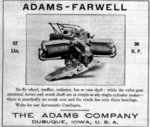
“An Adams-Farwell engine ad”
-Naturally, it also had its version to drive an airplane propeller (although in the picture below it appears with a test "grinder").
“Adams-Farwell aero engine”
-While slightly different in details, these aero engines were basically made like the Adams-Farwell land vehicle engines. Outstanding were their longitudinal cylinder fins, and on the frontside of the cylinders there were two double-ignition spark plugs.
“Rod connection without master”
“Connecting rod fastenings to the crankpin”
-Each rod big-end connects to the crankshaft, whose crank pin is longer to accommodate the five of them. The connecting rods are asymmetrical according to the place they occupy, but the circular sectioned rod beams are at the same height in the cylinder center.
-Below we have another PTO example through a bevel gear attached to the cylinder block. It is a terrestrial engine.
“Adams-Farwell car engine”
-The valve system is shown in the main text, but in the picture above we can see a small spring between the cylinder fins.
-The materials used in its construction naturally are of highest quality using chrome-nickel-vanadium wherever practicable.
-Un anuncio de ésta marca del año 1912 que aportamos al texto por tratarse de la versión aérea.
Below we show an ad of this brand from 1912. We include it in the text because it is an aero version.
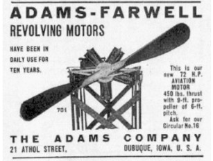
"Adams-Farwell ad"
Engines of ADAMS FARWELL
Model: 36 HP
"Adams Farwell at the NASM"
Model: KM-11
"Adams Farwell, vertical"
Model: Modelo de 280 HP
"Adams Farwell de 6 cylinders"