

Updated: 26-Feb-2019
With this name a pulsejet from 1913 is known.
-We received the information with two schematic drawings for the Hayot pulsejet.
It seems that because of its design it was destined to generate a thrust while acting as a sustainer on the extrados of a profile. The blown wing concept.

“Hayot profile application”
-The motor in this case is inserted inside the profile, near the leading edge as we see in the figure above.
-The engine itself we see in the following illustration, with the air intake under the engine (this would be under the profile in the mentioned assembly, the intrados) and the output above the profile, the extrados.
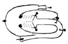
“Schematic diagram for Hayot's pulsejet”
-The incoming air is mixed with the fuel in the first injector. It is mentioned that the second injector introduces water.
-Then through some valves it flows into the combustion chamber where it burns and leaves on top.
-It works in a pulsating way, opening and closing the valves, repeating the cycle continuously, several times per second.
Engines of HAYOT
Model: Pulsoreactores de concepto especial
Arquitecture: Pulse jet
Chambers:
Fuels:
Feed System:
Ignition:
Thrust:
Weight: